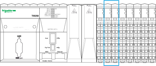
The following illustration shows the location of the Expert I/O of the controller:

The controller has 2 modules of Embedded Expert I/O. Each module is comprised of:
o5 fast inputs, 2 regular inputs and 2 fast outputs
o3 commons
Expert I/O modules support the following advanced functions:
oHigh speed counter (HSC)
oEvent input
oLatch input
oRun/Stop input
oPulse width modulation (PWM)
oFrequency generator
oAlarm output
The following illustration shows the wiring diagram of the expert I/O:

1 Internal electronics
2 24 Vdc Embedded expert modules power by external connection
The following illustration shows the wiring diagram of the expert I/O with encoder:

1 Internal electronics
2 24 Vdc Embedded expert modules power by external connection
3 Encoder
|
|
|
UNINTENDED EQUIPMENT OPERATION |
|
oUse shielded cables for all fast I/O, analog I/O, and communication signals. oGround cable shields for all fast I/O, analog I/O, and communication signals at a single point1. oRoute communications and I/O cables separately from power cables. |
|
Failure to follow these instructions can result in death, serious injury, or equipment damage. |
1Multipoint grounding is permissible (and in some cases inevitable) if connections are made to an equipotential ground plane dimensioned to help avoid cable shield damage in the event of power system short-circuit currents.
For more information, refer to the TM5 System Wiring Rules and Recommendation.
|
|
|
UNINTENDED EQUIPMENT OPERATION |
|
Do not connect wires to unused terminals and/or terminals indicated as “No Connection (N.C.)”. |
|
Failure to follow these instructions can result in death, serious injury, or equipment damage. |
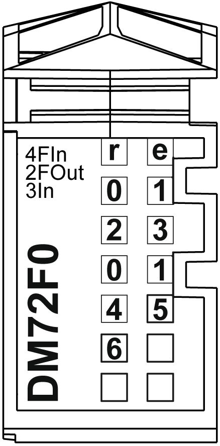
The following illustration shows the LEDs for the Expert I/O:

The table below describes the Expert I/O status LEDs:
|
LED |
Color |
Status |
Description |
|---|---|---|---|
|
r |
Green |
Off |
No power supply |
|
Single Flash |
Reset mode |
||
|
Flashing |
Preoperational mode |
||
|
On |
Normal operation |
||
|
e |
Red |
Off |
OK or no power supply |
|
Flashing |
Indicates a current overdraw on the module. |
||
|
On |
Module recovered from a power supply detected error. See configuration options in the controller programming guide. |
||
|
e+r |
Steady red / single green flash |
Invalid firmware |
|
|
0-3 |
Green |
On |
Input status of the corresponding input 0...3 |
|
0-1 |
Yellow |
On |
Output status of the corresponding output 0...1 |
|
4-6 |
Green |
On |
Input status of the corresponding input 4...6 |
|
|
|
UNINTENDED EQUIPMENT OPERATION |
|
Do not exceed any of the rated values specified in the environmental and electrical characteristics tables. |
|
Failure to follow these instructions can result in death, serious injury, or equipment damage. |
The following table describes the general characteristics of the embedded Expert modules:
|
General characteristics |
||
|---|---|---|
|
Input voltage range |
19.2...28.8 Vdc |
|
|
Rated voltage |
24 Vdc |
|
|
Isolation |
Between channels and internal bus |
See note 1 |
|
Between channels |
Not isolated |
|
|
Number of 0 Vdc commons |
3 (internally connected) |
|
|
24 Vdc I/O power segment current draw |
17 mA |
|
|
Internal power consumption |
0.4 W max. |
|
1 The isolation of the electronic module is 500 Vac RMS between the electronics powered by TM5 power bus and the part powered by 24 Vdc I/O power segment connected to the module. In practice, the TM5 electronic module is installed in the bus base, and there is a bridge between TM5 power bus and 24 Vdc I/O power segment. The two power circuits reference the same functional ground (FE) through specific components designed to reduce effects of electromagnetic interference. These components are rated at 30 Vdc or 60 Vdc. This effectively reduces isolation of the entire system from the 500 Vac RMS.