The digital DO12TE electronic module is equipped with 12 source outputs.
|
|
|
FIRE HAZARD |
|
oUse only the correct wire sizes for the maximum current capacity of the I/O channels and power supplies. oFor relay output (2 A) wiring, use conductors of at least 0.5 mm2 (AWG 20) with a temperature rating of at least 80 °C (176 °F). oFor common conductors of relay output wiring (7 A), or relay output wiring greater than 2 A, use conductors of at least 1.0 mm2 (AWG 16) with a temperature rating of at least 80 °C (176 °F). |
|
Failure to follow these instructions will result in death or serious injury. |
|
|
|
UNINTENDED EQUIPMENT OPERATION |
|
Do not exceed any of the rated values specified in the environmental and electrical characteristics tables. |
|
Failure to follow these instructions can result in death, serious injury, or equipment damage. |
For additional important information about fast output protection, refer to Protecting Outputs from Inductive Load Damage.
The following table describes the characteristics of the DO12TE electronic module:
|
Characteristic |
Value |
|
|---|---|---|
|
Output channels |
12 |
|
|
Wiring type |
1 wire |
|
|
Output type |
Transistor |
|
|
Signal type |
Source |
|
|
Output current |
0.5 A max. per output |
|
|
Total output current |
6 A max. |
|
|
Rated output voltage |
24 Vdc |
|
|
Output voltage range |
20.4 ... 28.8 Vdc |
|
|
De-rating at 60°C (140°F) |
I=0.4 A max. by channel |
|
|
Voltage drop |
0.3 Vdc max. at 0.5 A rated current |
|
|
Diagnostic status |
Output monitoring with 10 ms delay |
|
|
Leakage current when switched off |
5 µA |
|
|
Turn on time |
300 µs max. |
|
|
Turn off time |
300 µs max. |
|
|
Output protection |
Against short-circuit and overload, thermal protection |
|
|
Short-circuit output peak current |
12 A max. |
|
|
Automatic rearming after short-circuit or overload |
Yes, 10 ms min. depending on internal temperature |
|
|
Protection against reverse polarity |
Yes |
|
|
Clamping voltage |
Typ. 50 Vdc |
|
|
Switching frequency |
Resistive load |
500 Hz Max. |
|
Inductive load |
||
|
Isolation |
Between input and internal bus |
See note 1 |
|
Between channels |
Not isolated |
|
|
24 Vdc I/O segment current draw |
48 mA |
|
1 The isolation of the electronic module is 500 Vac RMS between the electronics powered by TM5 power bus and the part powered by 24 Vdc I/O power segment connected to the module. In practice, the TM5 electronic module is installed in the bus base, and there is a bridge between TM5 power bus and 24 Vdc I/O power segment. The two power circuits reference the same functional ground (FE) through specific components designed to reduce effects of electromagnetic interference. These components are rated at 30 Vdc or 60 Vdc. This effectively reduces isolation of the entire system from the 500 Vac RMS.
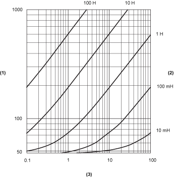
The following curves provide the switching inductive load characteristics for the DO12TE electronic module.

1 Coil resistance in Ω
2 Coil inductance
3 Max. operating cycles / second
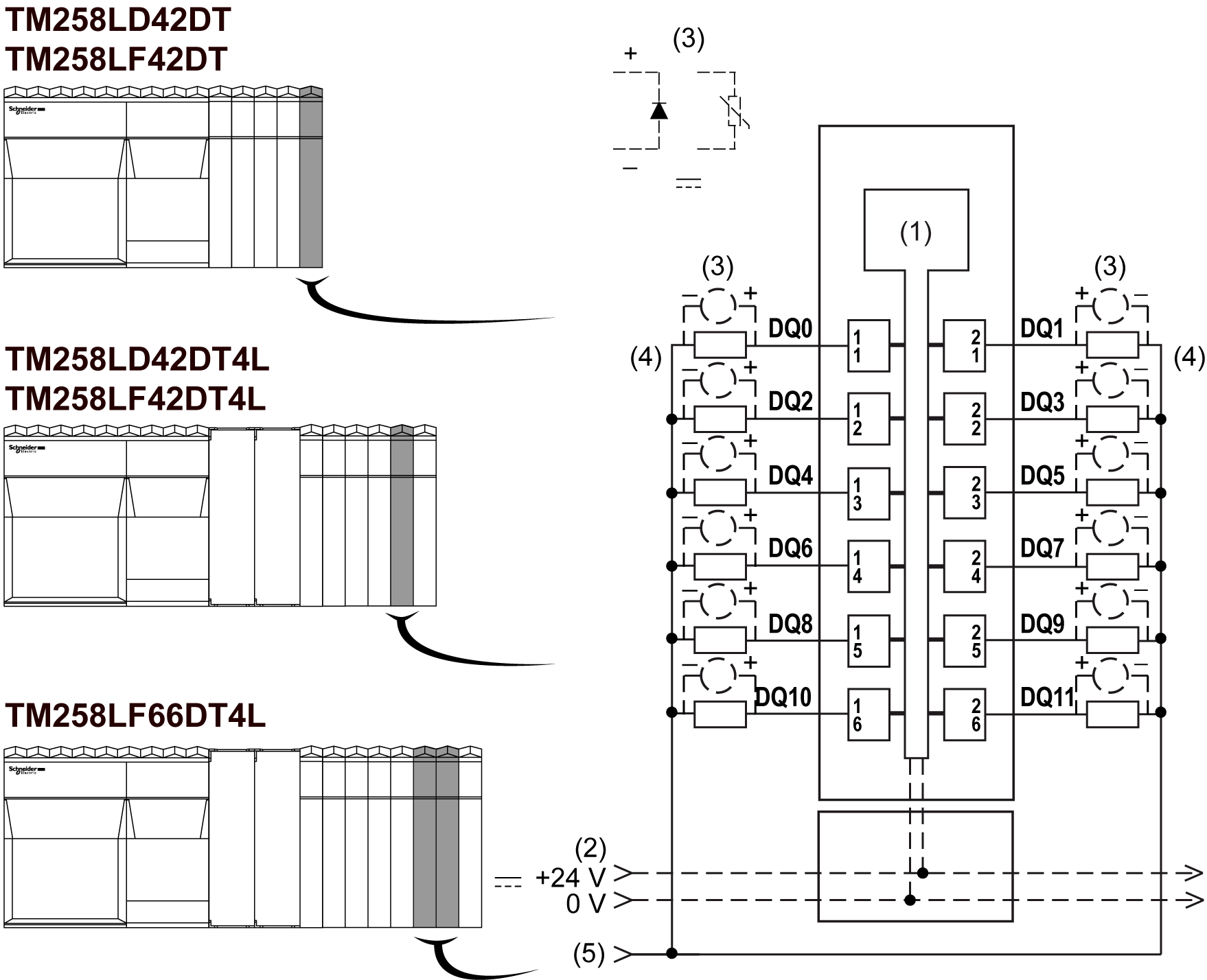
The following illustration shows the wiring diagram of the DO12TE:

1 Internal electronics
2 24 Vdc I/O power segment integrated into the bus bases
3 Inductive load protection
4 2-wire load
5 0 Vdc I/O power segment by external connection
NOTE: The assigned fuse values have been specified for the maximum current characteristics of the controller or expansion I/O and associated commons. You may have other considerations that are applicable based on the unique types of input and output devices you connect, or conformance to local, national or applicable certification regulations and standards, and you should size your fuses accordingly.
|
|
|
POTENTIAL EXPLOSION OR FIRE |
|
Connect the returns from the devices to the same power source as the 24 Vdc I/O power segment serving the module. |
|
Failure to follow these instructions can result in death, serious injury, or equipment damage. |
|
|
|
UNINTENDED EQUIPMENT OPERATION |
|
Do not connect wires to unused terminals and/or terminals indicated as “No Connection (N.C.)”. |
|
Failure to follow these instructions can result in death, serious injury, or equipment damage. |
The following illustration shows the LEDs for DO12TE:

The following table describes the DO12TE status LEDs:
|
LEDs |
Color |
Status |
Description |
|---|---|---|---|
|
r |
Green |
Off |
No power supply |
|
Single Flash |
Reset mode |
||
|
Flashing |
Preoperational mode |
||
|
On |
Normal operation |
||
|
e |
Red |
Off |
OK or no power supply |
|
Single flash |
Detected error for an output channel |
||
|
e+r |
Steady Red / Single Green flash |
Invalid firmware |
|
|
0- 11 |
Yellow |
Off |
Corresponding output deactivated |
|
On |
Corresponding output activated |
||