Characteristics of the Controller Power Distribution Module
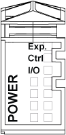
The Controller Power Distribution Module (CPDM) has three 24 Vdc power connections:
oMain power (Ctrl)
oExpert I/O power (Exp.)
o24 Vdc I/O Power Segment power (I/O)
The state of these three power connections is indicated by a set of LEDs on the CPDM:
The following table describes the CPDM LED display:
|
LEDs |
Color |
Status |
Description |
|---|---|---|---|
|
Exp (Expert I/O power) |
Green |
On |
24 Vdc applied |
|
Ctrl (Main power) |
Green |
On |
24 Vdc applied |
|
I/O (24 Vdc I/O Power Segment power) |
Green |
On |
24 Vdc applied |
The Main power serves the TM5 power bus, the Serial Line port, the USB port, any PCI modules that may be installed, and power for the controller electronics.
The Expert I/O power serves the Expert I/O module inputs and outputs, the power for the embedded Encoder port, and power for the Expert I/O module electronics.
The 24 Vdc I/O power segment power serves the Regular I/O modules inputs and outputs, as well as providing power to the first segment of the 24 Vdc I/O Power segment for any optional I/O slices of the local configuration.
CPDM Power Consumption Overview
The following table shows the power characteristics of the TM258LF42DT4L:
|
Rated voltage CPDM |
24 Vdc |
|||
|
Voltage range CPDM |
20.4...28.8 Vdc |
|||
|
Main power |
Minimum current (no external loads) |
0.3 A |
||
|
Maximum current including the following loads: |
1.2 A |
|||
|
|
Current for TM5 bus power when adding expansion modules |
0...0.1 A |
||
|
Current for serial line when connected devices consume power |
0...0.05 A |
|||
|
Current for USB Host when connected devices consume power |
0...0.1 A |
|||
|
Current for optional PCI modules when connected devices consume power |
Refer to your specific PCI module |
|||
|
Inrush current |
Time < 70 µs |
100 A max. |
||
|
70...2000 µs |
3 A max. |
|||
|
Internal protection |
No |
see note 1 |
||
|
Embedded Expert modules power |
Minimum current (no external loads) |
0.04 A |
||
|
Maximum current including the following loads: |
0.9 A |
|||
|
|
Current for Expert Inputs |
0...0.1 A |
||
|
Current for Expert Outputs |
0...0.8 A |
|||
|
Inrush current |
Time < 150 µs |
50 A max. |
||
|
Internal protection |
No |
see note 1 |
||
|
24 Vdc I/O power segment |
Maximum current (depending on the modules on the segment) |
10 A max. |
||
|
Inrush current (depending on the modules on the segment) |
Time < 500 µs |
25 A max. |
||
|
Internal protection |
No |
see note 1 |
||
1 Add external fuse as specified in the wiring diagrams.
Refer to the chapter Example 1: Current Consumed by a Local Configuration for further details on power consumption.