The following illustration shows the location of the encoder interface of the controller:
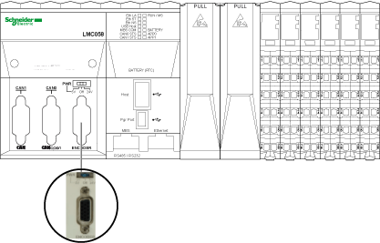
The encoder interface supports both Incremental and Absolute (SSI) connections.
The encoder interface can provide and control the encoder power supply.
The encoder interface consists of a 15-pin Sub-D HD connector and a voltage supply selector as shown below:

1 Selection of power distribution
2 Encoder interface connector
The illustration below shows the 3 different positions of the switch:
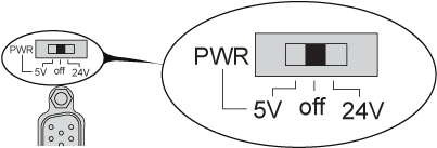
The switch allows the user to select one of the following voltages:
o+5 Vdc
oNo power distribution delivered
o+24 Vdc
The table below shows the voltage supplied to pins 7 and 15:
|
Encoder Interface Switch Position |
Pin 15 |
Pin 7 |
|---|---|---|
|
5V |
5 Vdc |
0 Vdc |
|
OFF |
0 Vdc |
0 Vdc |
|
24V |
0 Vdc |
24 Vdc |
|
NOTICE |
|
LOSS OF ENCODER POWER |
|
oVerify the position of the encoder interface switch before applying power to the controller. oDo not change the position of the encoder interface switch when the controller is powered. |
|
Failure to follow these instructions can result in equipment damage. |
The table below shows the characteristics of the encoder:
|
Characteristics |
Description |
|
|---|---|---|
|
Incremental |
Type of signals |
A+, A-, B+, B-, Z+, Z- |
|
Maximum operating frequency |
200 kHz per input x 4, or 1 MHz for counting |
|
|
SSI |
Clock voltage |
5 Vdc |
|
Clock frequency |
200 KHz |
|
NOTE: Calculation of Maximum Cable Length
Max. cable length [m] = Max. voltage drop for the cable [V] x Wire cross section (mm2) / (Encoder current [A] x 0.0171 (Ω mm²/m])
where:
Max. voltage drop for the cable = (Min. module output voltage - Min. encoder input voltage) / 2
Example:
Encoder consumes 100 mA with a 4.5…5.5 V supply
Min. module output voltage = 5.1 Vdc x 0.95 = 4.845 Vdc
Max. voltage drop for the cable = (4.845 Vdc - 4.5 Vdc) / 2 = 0.1725 Vdc
Max. cable length 0.14 mm2 = 0.1725 x 0.14 / (0.1 x 0.0171) = 14 m
Max. cable length 0.50 mm2 = 0.1725 x 0.50 / (0.1 x 0.0171) = 50 m
The encoder interface consists of a 15-pin Sub-D HD connector.
The following illustration describes the pins numbering:

The following table describes the pins of the encoder:
|
Description |
Encoder |
Pin |
VW3M4701 option wire colors |
|---|---|---|---|
|
Incremental encoder |
A+ |
1 |
red/white |
|
A- |
2 |
brown |
|
|
Z+ |
4 |
orange |
|
|
Z- |
5 |
yellow |
|
|
B+ |
10 |
white |
|
|
B- |
11 |
purple |
|
|
Absolute (SSI) encoder |
SSI data + |
1 |
red/white |
|
SSI data - |
2 |
brown |
|
|
CLKSSI + |
6 |
green |
|
|
CLKSSI - |
14 |
light brown |
|
|
5 V Encoder supply |
+ 5 Vdc |
15 |
light purple |
|
0 Vdc |
8 |
pink |
|
|
24 V Encoder supply |
+ 24 Vdc |
7 |
blue |
|
0 Vdc |
8 |
pink |
|
|
Encoder power distribution feedback |
Supply return |
13 |
light green |
|
Shielding |
|
Shell |
cable braided shield |
The table below shows the current supplied to pins 7 and 15:
|
Pin |
Supplied current |
Voltage |
Voltage range |
|---|---|---|---|
|
7 |
170 mA |
24 Vdc |
11...30 Vdc |
|
15 |
150 mA |
5 Vdc |
4...6 Vdc |
NOTE: The encoder connector is supplied by the Expert I/O Power Distribution. Please refer to Embedded Expert I/O.
A supply return signal from the encoder enables detection of encoder disconnection and allows your program to check if the encoder is still powered.
The following illustration describes the wiring diagram of an encoder (RS422 / 24 Vdc) mounted on the encoder interface:
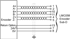
The following illustration describes the wiring diagram of an encoder (RS422 / 5 Vdc or push-pull) mounted on the encoder interface:
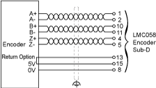
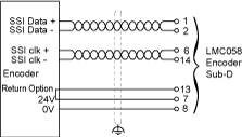
The following illustration describes the wiring diagram of an encoder (SSI) mounted on the encoder interface:
