This section describes the characteristics of the TM5SDO2DTRFS module. See also TM5 Environmental Characteristics.
|
|
|
FIRE HAZARD |
|
oUse only the correct wire sizes for the current capacity of the I/O channels and power supplies. oFor relay output (2 A) wiring, use conductors of at least 0.5 mm2 (AWG 20) with a temperature rating of at least 80 °C (176 °F). oFor common conductors of relay output wiring (6 A), or relay output wiring greater than 2 A, use conductors of at least 1.0 mm2 (AWG 16) with a temperature rating of at least 80 °C (176 °F). |
|
Failure to follow these instructions will result in death or serious injury. |
|
|
|
UNINTENDED EQUIPMENT OPERATION |
|
Do not exceed any of the rated values specified in the environmental and electrical characteristics tables. |
|
Failure to follow these instructions can result in death, serious injury, or equipment damage. |
The following table lists the general characteristics of the TM5SDO2DTRFS module:
|
General characteristics |
||
|---|---|---|
|
Rated power supply voltage |
24 Vdc |
|
|
Status indicators |
oI/O functions per channel ooperating state omodule status |
|
|
Diagnostics |
module run and detected error |
indicated by status LED indicator and software status |
|
inputs |
indicated by status LED indicator |
|
|
outputs |
indicated by status LED indicator and software status (detected output error status) |
|
|
Electrical isolation1) |
channel - bus |
See note. |
|
channel - channel |
See note. |
|
|
TM5 Bus 5 Vdc current draw |
52 mA |
|
|
24 Vdc I/O segment current draw |
47.9 mA |
|
|
Certifications and standards |
oCE ocULus oEN IEC 61508:2010 oEN IEC 62061:2010 oEN ISO 13849-1:2008 oEN IEC 61511:2004 oEN 50156-1:2004 Relay: oEN 50155 oEN 50205 |
|
|
Maximum internal cycle time |
500 µs |
|
|
200 µs |
||
|
500 µs |
||
|
Id code for firmware update |
53765 dec |
|
NOTE (1) The isolation of the electronic module is 500 Vac RMS between the electronics power by the TM5 bus and those powered by 24 Vdc I/O power segment connected to the module. In practice, the electronic module is installed in the bus base, and there is a bridge between the TM5 power bus and the 24 Vdc I/O power segment. The two power circuits reference the same functional ground (FE) through specific components designed to reduce effects of electromagnetic interference. These components are rated at 30 Vdc or 60 Vdc. This effectively reduces isolation of the entire system from the 500 Vac RMS.
The following table lists the operating conditions for the TM5SDO2DTRFS module:
|
Operating conditions |
||
|---|---|---|
|
Mounting orientation |
horizontal or vertical |
|
|
Operating temperature |
horizontal installation |
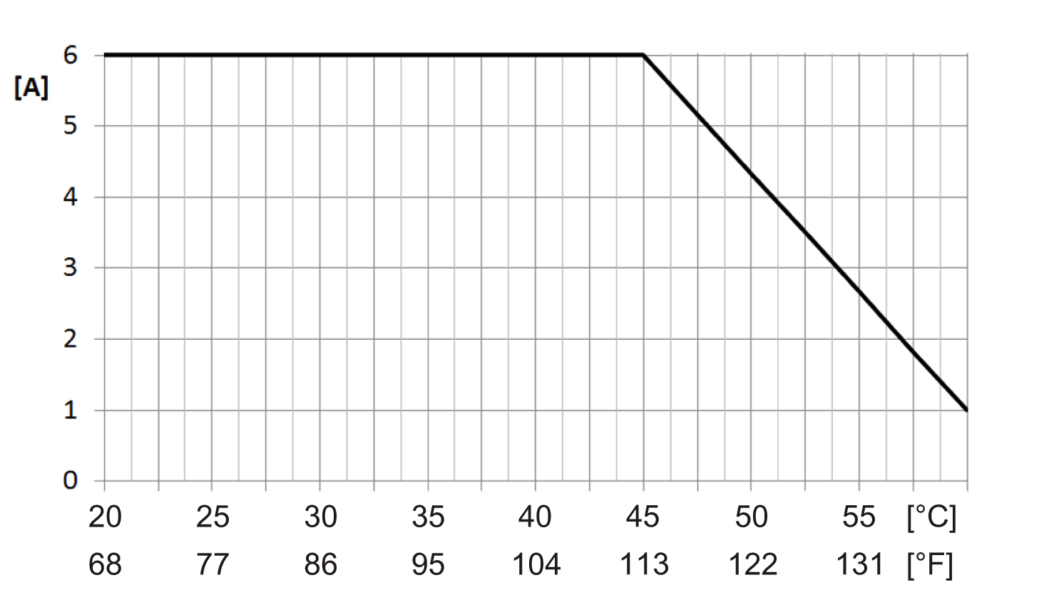
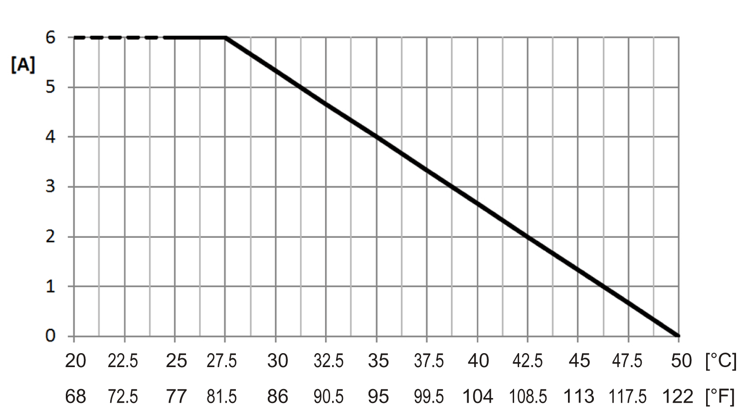
0...+55 °C (+32...131 °F), for derating refer to following table1 |
|
vertical installation |
0...+45 °C (+32...113 °F), for derating refer to following table1 |
|
|
Relative humidity |
5...95%, non-condensing |
|
|
Installation at altitudes above sea level: |
0 up to 2000 m (0 up to 6561 ft) |
no derating for altitude |
|
> 2000 m (>6561 ft) |
reduction of ambient temperature by 0.5 °C per 100 m (0.9 °F per 328 ft) |
|
|
EN 60529 Protection type |
IP20 |
|
1 Derating in relation to operating temperature and mounting orientation:
|
Horizontal installation, 0...+55 °C (+32...131 °F) |
Vertical installation, 0...+45 °C (+32...113 °F) |
|---|---|

X-axis: Ambient temperature [°C/°F] Y-axis: Output current [A] |

X-axis: Ambient temperature [°C/°F] Y-axis: Output current [A] |
|
NOTE: If a TM5SD000 is installed on the side of the module, the horizontal installation derating is shifted to the right by the following derating bonus: oTM5SD000 to the left: +0 °C (+0 °F) oTM5SD000 to the right: +2.5 °C (+4.5 °F) oTM5SD000 to the left and right: +2.5 °C (+4.5 °F) |
NOTE: Using a TM5SD000 does not provide a derating bonus in vertical installation. |
Storage and Transport Conditions
The following table lists the storage and transport conditions for the TM5SDO2DTRFS module:
|
Storage and transport conditions |
|
|---|---|
|
Temperature |
-25...+70 °C (-13...+158 °F) |
|
Relative humidity |
5...95%, non-condensing |
The following table lists the relay output characteristics of the TM5SDO2DTRFS module:
|
Relay output |
|||
|---|---|---|---|
|
Switching voltage range |
5...24 Vdc, 5...230 Vac |
||
|
Switching current range |
5...6000 mA |
||
|
Turn-around time on relay |
maximum 50 ms |
||
|
Design |
o1 normally open contact ointernal high-side and low-side control |
||
|
Coil voltage |
24 Vdc (-15% / +20%) |
||
|
Contact resistance (without terminal block) |
typical: 20 mΩ |
||
|
Maximum switching capacity |
AC1 |
230 Vac / 6 A |
|
|
AC15 |
230 Vac / 3 A |
||
|
DC1 |
24 Vdc / 6 A |
||
|
DC13 |
24 Vdc / 5 A / 0.1 Hz |
||
|
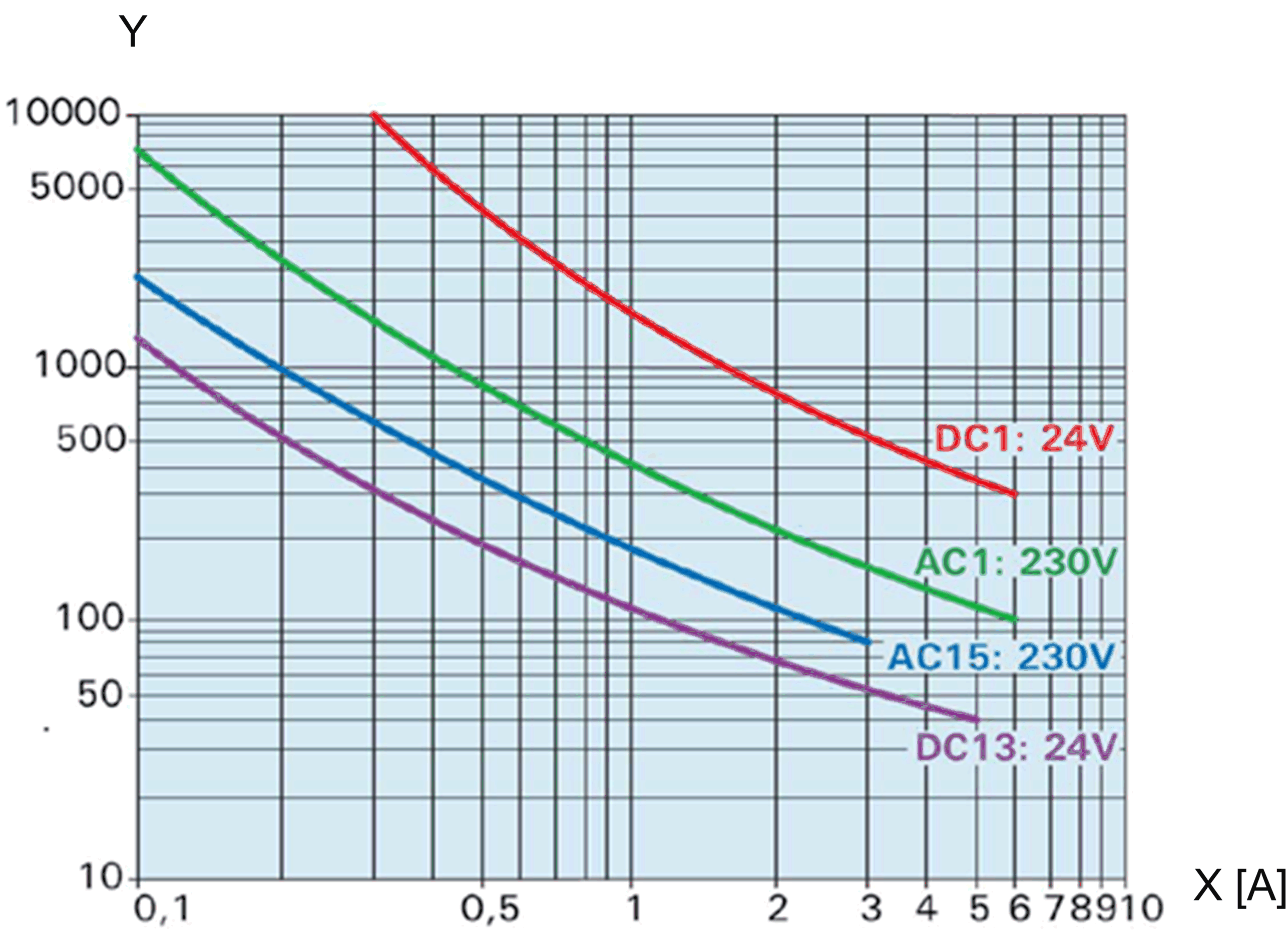
Contact lifespan |

X-axis: switching current (A) Y-axis: switching cycle x 1000 |
||
|
Peak (inrush) current |
30 A for 20 ms |
||
|
Overvoltage category in accordance with EN 60664-1 |
II |
||
|
The outputs must be protected against overload and short-circuit with an external fuse. |
external 6 A gL/gG fuse (slow-blow fuse), LS circuit breaker C characteristic 1.6 A |
||
|
Isolation voltage between channel and bus1) |
See note. |
||
|
Isolation voltage between channel and channel |
230 Vac |
||
NOTE (1) The isolation of the electronic module is 300 Vac RMS between the electronics power by the TM5 bus and those powered by 24 Vdc I/O power segment connected to the module. In practice, the electronic module is installed in the bus base, and there is a bridge between the TM5 power bus and the 24 Vdc I/O power segment. The two power circuits reference the same functional ground (FE) through specific components designed to reduce effects of electromagnetic interference. These components are rated at 30 Vdc or 60 Vdc. This effectively reduces isolation of the entire system from the 300 Vac RMS.
Safety-Related Characteristics
The following table lists the safety-related characteristics of the TM5SDO2DTRFS module:
|
Criteria |
Characteristic value for relay channel |
|
|---|---|---|
|
Maximum performance level according to EN ISO 13849-1:2008 PL |
oPL c if the relay channel is used independently oPL e if both relay channels are connected in series |
|
|
Category according to EN ISO 13849-1:2008 |
oCAT 1 if the relay channel is used independently oCAT 4 if both relay channels are connected in series |
|
|
Maximum safety integrity level according to EN IEC 62061:2010 |
SIL 3 if both relay channels are connected in series |
|
|
Maximum safety integrity level according to EN IEC 61508:2010 |
SIL 3 if both relay channels are connected in series |
|
|
Maximum safety integrity level according to EN IEC 61511:2004 |
SIL 3 if both relay channels are connected in series |
|
|
oB10d at DC1 o6 A o24 Vdc |
780,000 cycles |
|
|
oB10d at AC1 o6 A o230 Vac |
780,000 cycles |
|
|
oB10d at AC15 o3 A o230 Vac |
1,960,000 cycles |
|
|
oB10d at DC13 o5 A o24 Vdc |
780,000 cycles |
|
|
>90% |
||
|
20 years |
||
NOTE: The B10d values only apply when the relay is activated at least once a year.