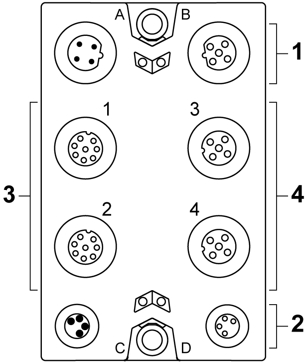
The following figure presents the connection elements for the TM7SDI8DFS:

|
Number |
Meaning |
|---|---|
|
1 |
oTM5 link o2 x M12 (4-pin) oconnector A: input oconnector B: output |
|
2 |
oModule supply 24 Vdc o2 x M8 (4-pin) oconnector C: supply feed oconnector D: routing |
|
3 |
Connectors 1 and 2: oDigital I/O: 2 x M12 (8-pin) |
|
4 |
Connectors 3 and 4: oDigital I/O: 2 x M12 (5-pin) |
The pin assignments of the power and communication connectors (A, B, C and D) are provided in the TM7 Physical Description.
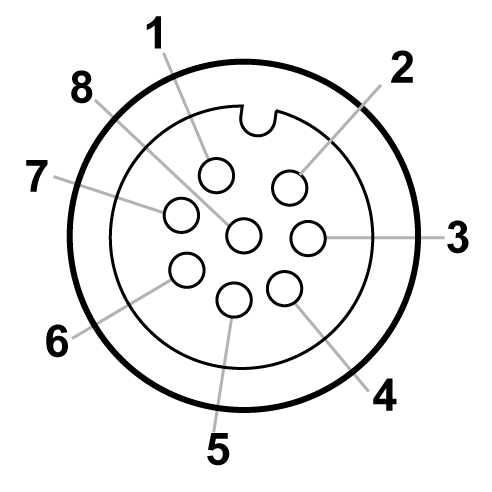
Pin assignment for the 8-pin I/O connectors 1 and 2 of the TM7SDI8DFS module:

1 +24 Vdc
2 Test (pulse) output 1
3 COM
4 SI x (safety-related inputs)
5 DI x
6 Test (pulse) output 2
7 SI x (safety-related inputs)
8 DO x (non-safety-related outputs)
|
Connector socket |
Pin1 |
Pin2 |
Pin3 |
Pin4 |
Pin5 |
Pin6 |
Pin7 |
Pin8 |
|---|---|---|---|---|---|---|---|---|
|
1 (IN/OUT) |
+24 Vdc |
Test (pulse) output 1 |
COM |
SI 1 |
DI 1 |
Test (pulse) output 2 |
SI 2 |
DO 1 |
|
2 (IN/OUT) |
+24 Vdc |
Test (pulse) output 1 |
COM |
SI 3 |
DI 2 |
Test (pulse) output 2 |
SI 4 |
DO 2 |
NOTE: Test (pulse) output 1 and test (pulse) 2 are shared between the connector sockets 1, 2, 3 and 4.
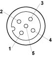
Pin assignment for the 5-pin I/O connectors 3 and 4 of the TM7SDI8DFS module:

1 Test (pulse) x
2 SI x (safety-related inputs)
3 COM
4 SI x (safety-related inputs)
5 Test (pulse) x (inputs)
|
Connector socket |
Pin1 |
Pin2 |
Pin3 |
Pin4 |
Pin5 |
|---|---|---|---|---|---|
|
3 (IN) |
Test (pulse) 1 |
SI 5 |
COM |
SI 6 |
Test (pulse) 2 |
|
4 (IN) |
Test (pulse) 1 |
SI 7 |
COM |
SI 8 |
Test (pulse) 2 |
NOTE: Test (pulse) output 1 and test (pulse) 2 are shared between the connector sockets 1, 2, 3 and 4.
NOTE: Cross-circuits between the two channels of a connector cannot be ruled out according to ISO 13849-1. This is why shared error handling is implemented for both channels of a connector. This means that both channels are switched off as soon as an error has been detected on one channel.
Detected errors are acknowledged in a similar way. As soon as a detected channel error has been acknowledged, the error state on the other channel of the same connector is also acknowledged.
However, the restart inhibit is separately active for each channel to help prevent unintentional enabling of a channel.
|
|
|
IP67 NON-CONFORMANCE |
|
oProperly fit all connectors with cables or sealing plugs and tighten for IP67 conformance according to the torque values as specified in this document. oDo not connect or disconnect cables or sealing plugs in the presence of water or moisture. |
|
Failure to follow these instructions can result in death, serious injury, or equipment damage. |