The TMSES4 Ethernet module provides an additional Ethernet interface to the controller. A maximum of three TMSES4 modules can be configured in the system.
The MAC address of the TMSES4 is unique for the three TMSES4, this MAC address is available on the label on the left side of the M262 Logic/Motion Controller.
The table describes the main characteristics of the TMSES4 Ethernet communication module:
|
Main Characteristics |
|
|---|---|
|
Standard |
|
|
Connector type |
4 RJ45 connectors for Ethernet communication |
|
Transfer rate |
1 Gbit/s maximum |
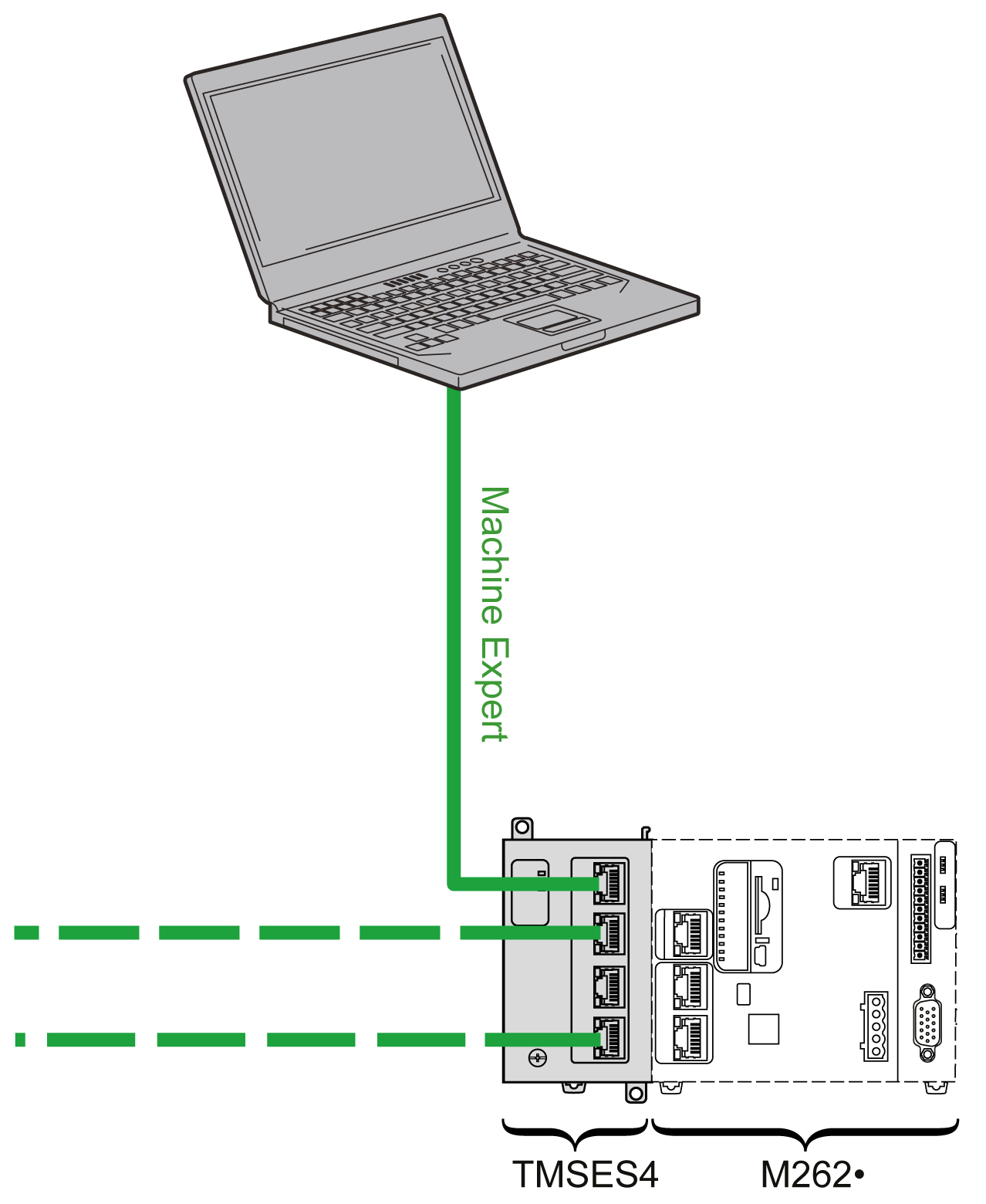
The following illustration shows the connection of a controller to an Ethernet network:

NOTE: If you configure several TMSES4 modules, each module must be on a different subnetwork.
NOTE: TMSES4 modules must be on a different subnetwork than the controller Ethernet ports.
NOTE: Never connect two TMSES4 modules together if they are mounted on the same controller.
NOTE: Never connect a TMSES4 module to an Ethernet port on the controller on which it is mounted.
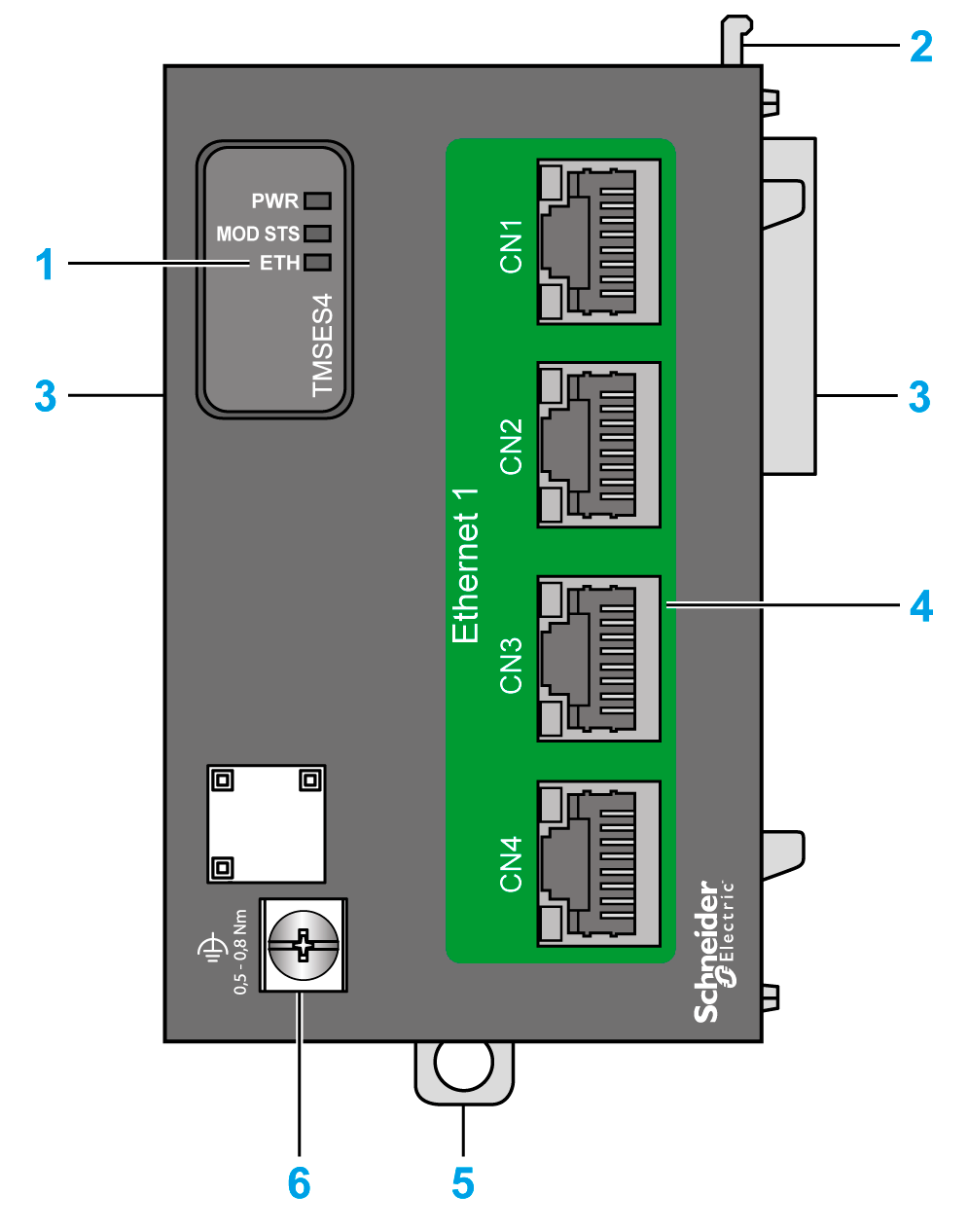
The following illustration shows the main elements of the TMSES4 module:

|
Label |
Description |
|---|---|
|
1 |
Status LEDs |
|
2 |
Locking device |
|
3 |
TMS bus connector |
|
4 |
4 Ethernet ports |
|
5 |
Clip-on lock for 35 mm (1.38 in.) top hat section rail (DIN rail) |
|
6 |
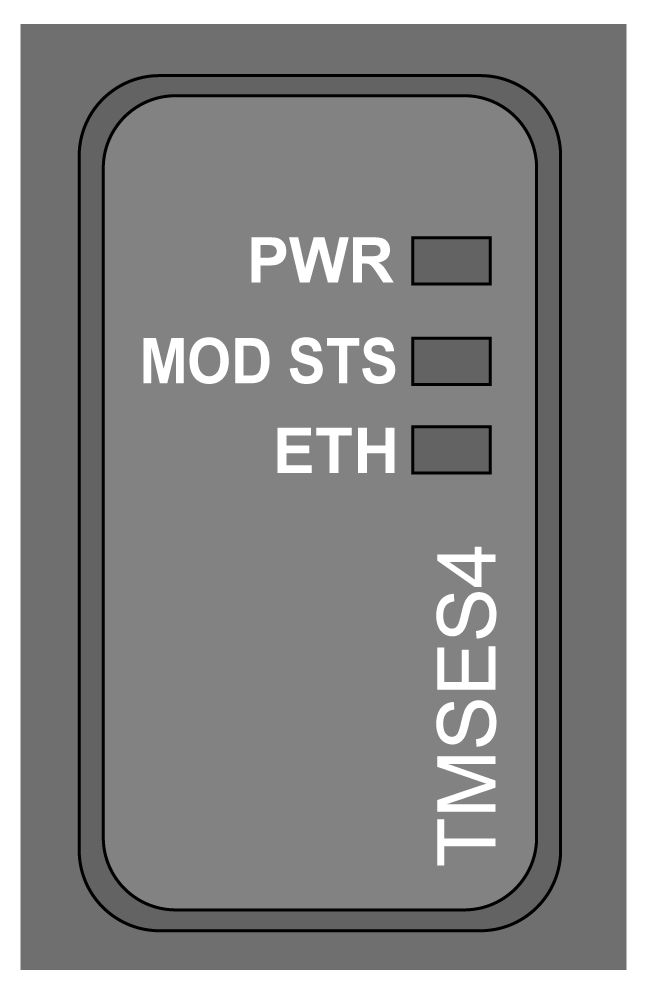
The illustration shows the TMSES4 status LEDs:

The table describes the TMSES4status LED:
|
LED |
Color |
Status |
Description |
|---|---|---|---|
|
PWR |
Green |
On |
Power is applied. |
|
Off |
Power is removed. |
||
|
MOD STS |
Green |
On |
The module is running. |
|
Red |
On |
The module is not running. |
|
|
Flashing |
A connection error is detected. |
||
|
ETH |
Green |
On |
The module is running and one port is connected. |
|
Flashing |
If flashing: o3 times: no ports are connected. o4 times: IP address is duplicated. o5 times: IP address is awaiting. o6 times: default IP address is applied. |
||
|
Off |
The module is initializing. |
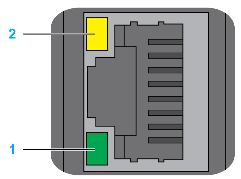
The illustration shows the RJ45 connector status LEDs:

The table describes the RJ45 connector status LED:
|
Label |
Description |
LED |
||
|---|---|---|---|---|
|
Color |
Status |
Description |
||
|
1 |
Ethernet activity |
Green |
Off |
No activity |
|
On |
Transmitting or receiving data |
|||
|
2 |
Ethernet link |
Green/Yellow |
Off |
No link |
|
Yellow |
Link at 10 or 100 Mbit/s |
|||
|
Green |
Link at 1 Gbit/s |
|||