Box iPC and AC Power Supply Module Installation
Installing the AC Power Supply Module (HMIYMMAC1)
Before installing an AC power supply module (HMIYMMAC1), shut down Windows operating system in an orderly fashion and remove all power from the device.
|
|
|
HAZARD OF ELECTRIC SHOCK, EXPLOSION OR ARC FLASH |
|
oRemove all power from the device before removing any covers or elements of the system, and prior to installing or removing any accessories, hardware, or cables. oUnplug the power cable from both the Magelis Industrial PC and the power supply. oAlways use a properly rated voltage sensing device to confirm that power is off. oReplace and secure all covers or elements of the system before applying power to the unit. oUse only the specified voltage when operating the Magelis Industrial PC. The AC unit is designed to use 100...240 Vac input. |
|
Failure to follow these instructions will result in death or serious injury. |
|
|
|
OVERTORQUE AND LOOSE HARDWARE |
|
oDo not exert more than 0.5 Nm (4.5 lb-in) of torque when tightening the installation fastener, enclosure, accessory, or terminal block screws. Tightening the screws with excessive force can damage the installation fastener. oWhen fastening or removing screws, ensure that they do not fall inside the Magelis Industrial PC chassis. |
|
Failure to follow these instructions can result in injury or equipment damage. |
|
Step |
Action |
|---|---|
|
1 |
Remove all power from the Box iPC and confirm that the power adapter has been disconnected from its power source. |
|
2 |
Box iPC Universal/Performance (HMIBMU/HMIBMP): Mount the AC power supply module on the Box iPC Universal/Performance with four screws (the power switch cover and the AC IN connector have to be removed): 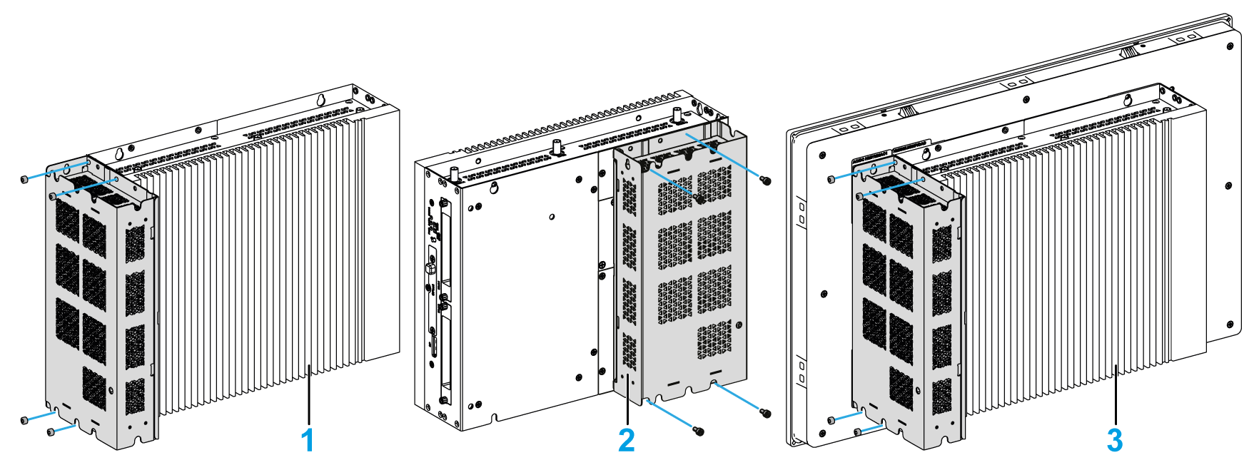
1 Box iPC (wall mounting) without display 2 Box iPC (book mounting) without display 3 Box iPC 2-Slot with display Box iPC Optimized (HMIBMI/HMIBMO): Mount the AC power supply module on the Box iPC Optimized with two screws (the power switch cover and the AC IN connector have to be removed): 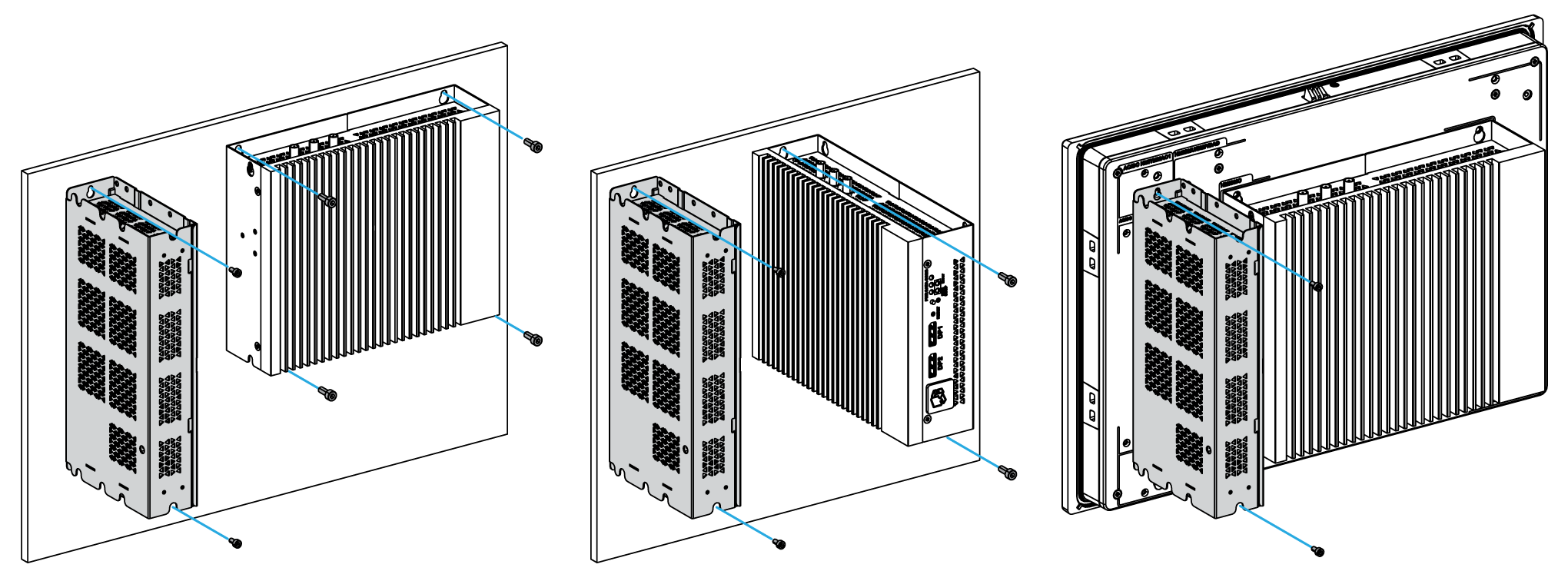
1 Box iPC (wall mounting) without display (the AC power supply module is installed separately in the cabinet) 2 Box iPC (book mounting) without display (the AC power supply module is installed separately in the cabinet) 3 Box iPC Regular with display NOTE: oThe recommended torque to tighten these screws is 0.5 Nm (4.5 lb-in). oTo mount the Box iPC with display in the control cabinet, see Box iPC installation. |
|
3 |
Remove the terminal block from the power connector on the Box and connect one side of the DC power cable to the terminal block: 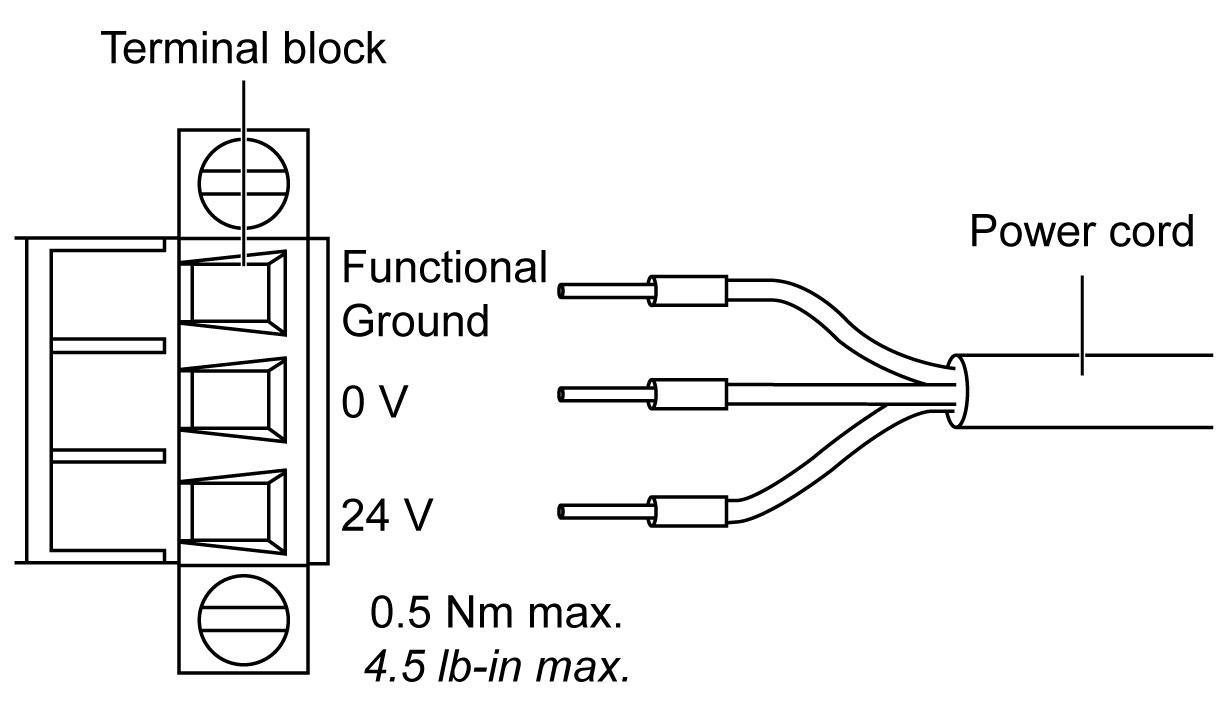
|
|
4 |
Place the terminal block in the power connector of the Box iPC and tighten the screws: 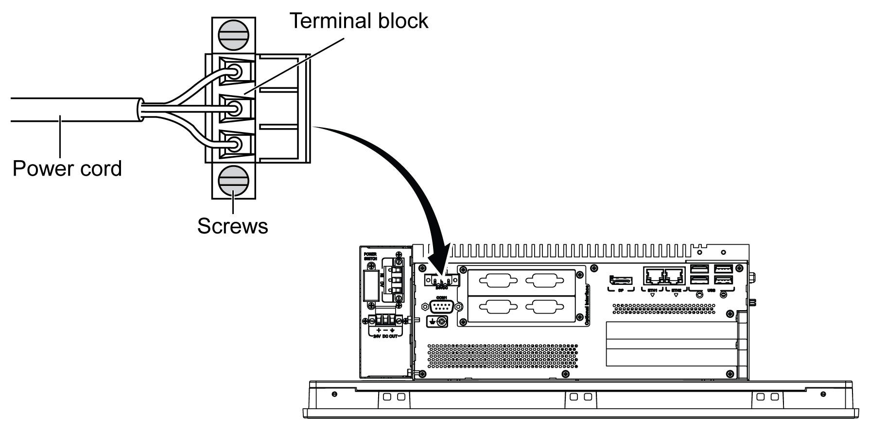
NOTE: The recommended torque to tighten these screws is 0.5 Nm (4.5 lb-in). |
|
5 |
Connect the other side of DC power cable with the terminal block attached to 24 V DC OUT of the AC power supply module and tighten the screws: 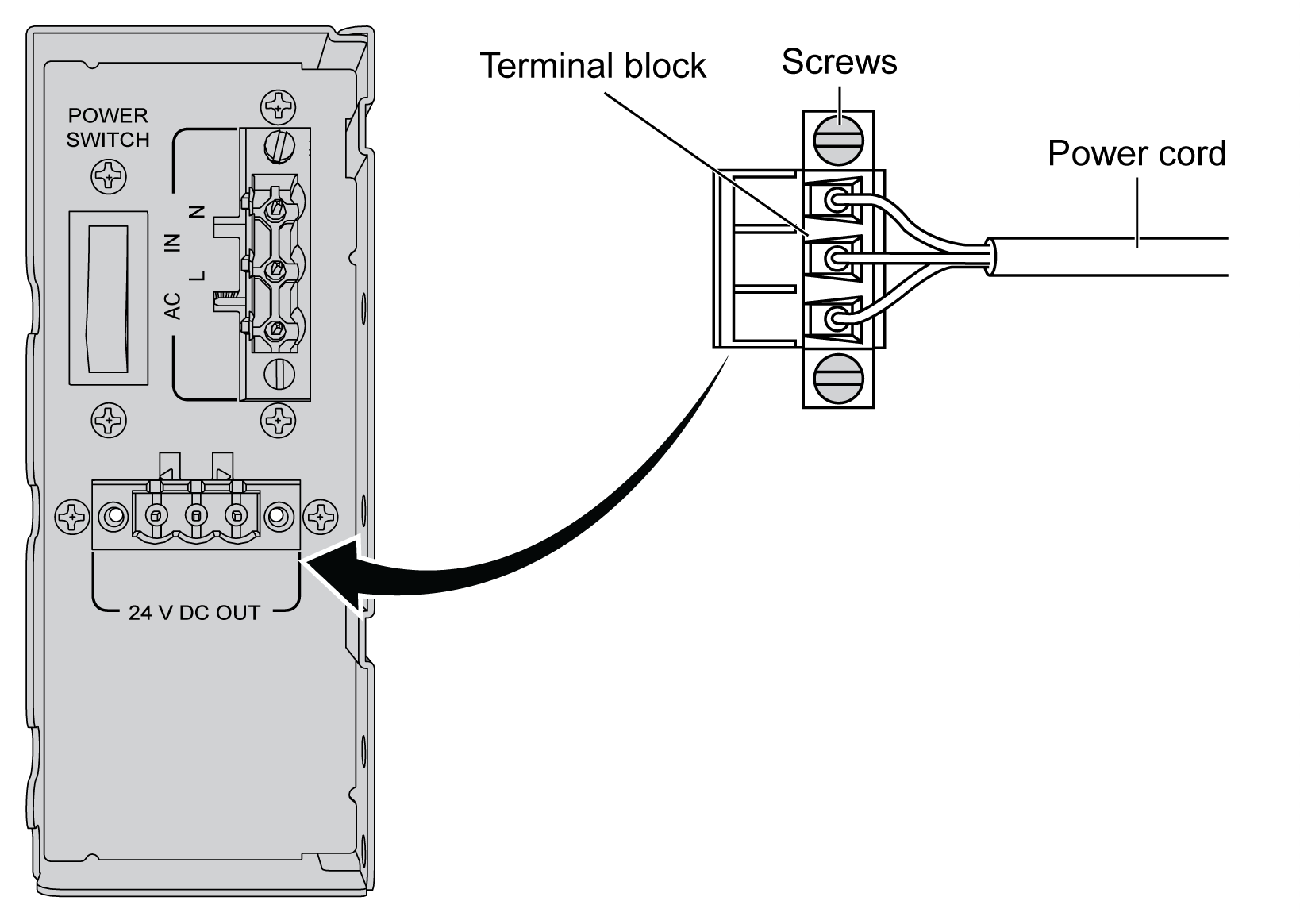
Use copper wire rated for 75 °C (167 °F) with a section of 0.75 to 2.5 mm2 (AWG 18 to AWG 14). |
|
6 |
Connect the AC power cable with the terminal block attached to AC IN of the AC power supply module from its power source: 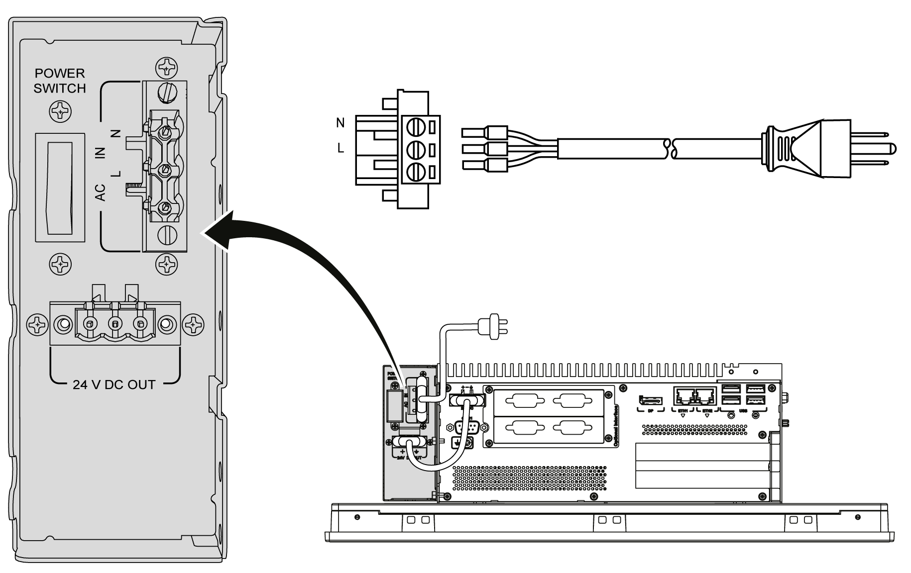
|
Installing the AC Power Supply Module (HMIYPSOMAC1) with the Box iPC Optimized (HMIBMI/HMIBMO)
Follow these steps when installing the AC power supply module (HMIYPSOMAC1):
|
Step |
Action |
|---|---|
|
1 |
Remove all power from the Box iPC Optimized and confirm that the power adapter is disconnected from its power source. |
|
2 |
Box iPC Optimized without VESA kit: The AC power supply module is mounted to the Box iPC Optimized with four screws M3 x 4: 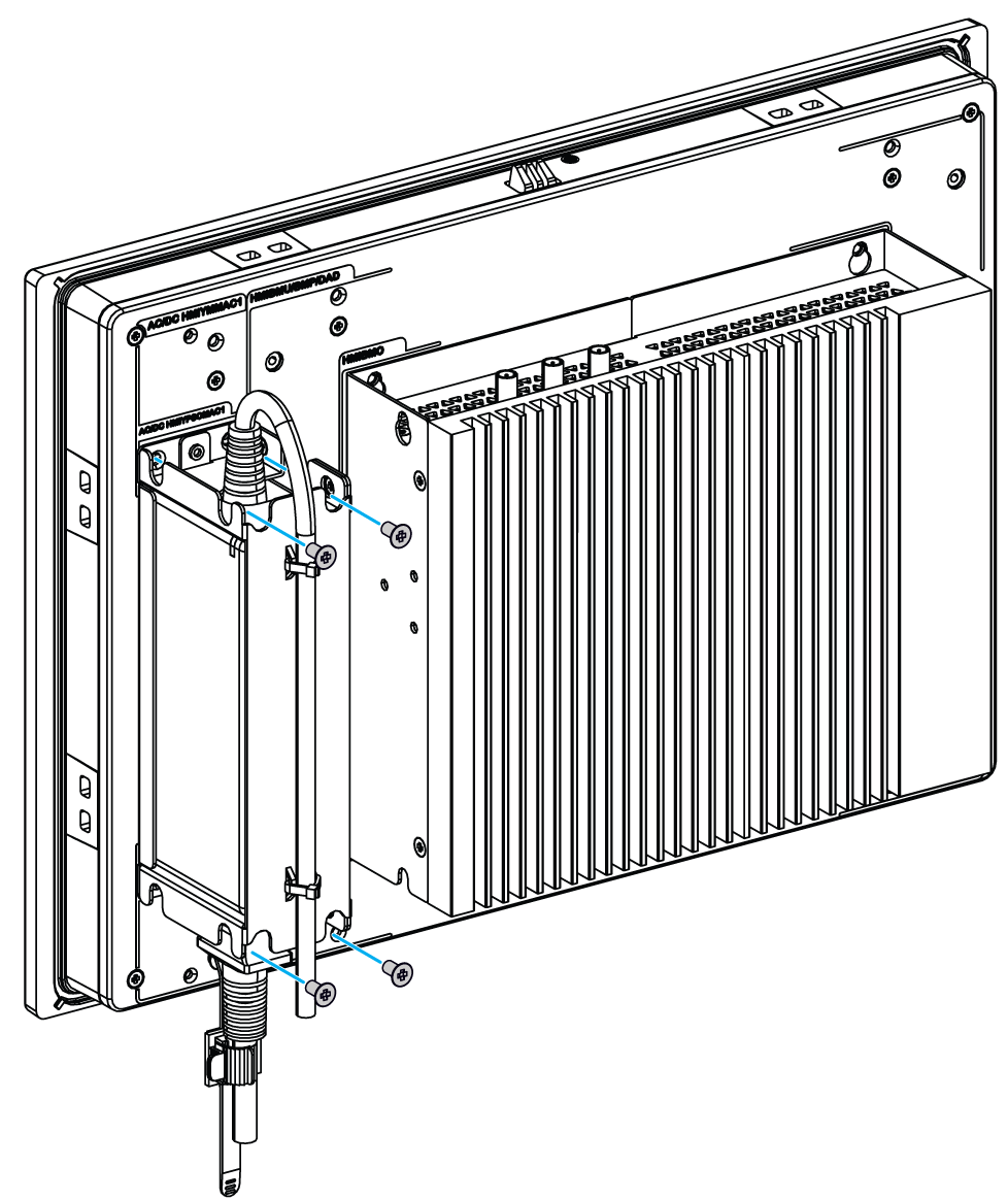
Box iPC Optimized with VESA kit: The AC power supply module is mounted to the VESA with four screws M3 x 4: 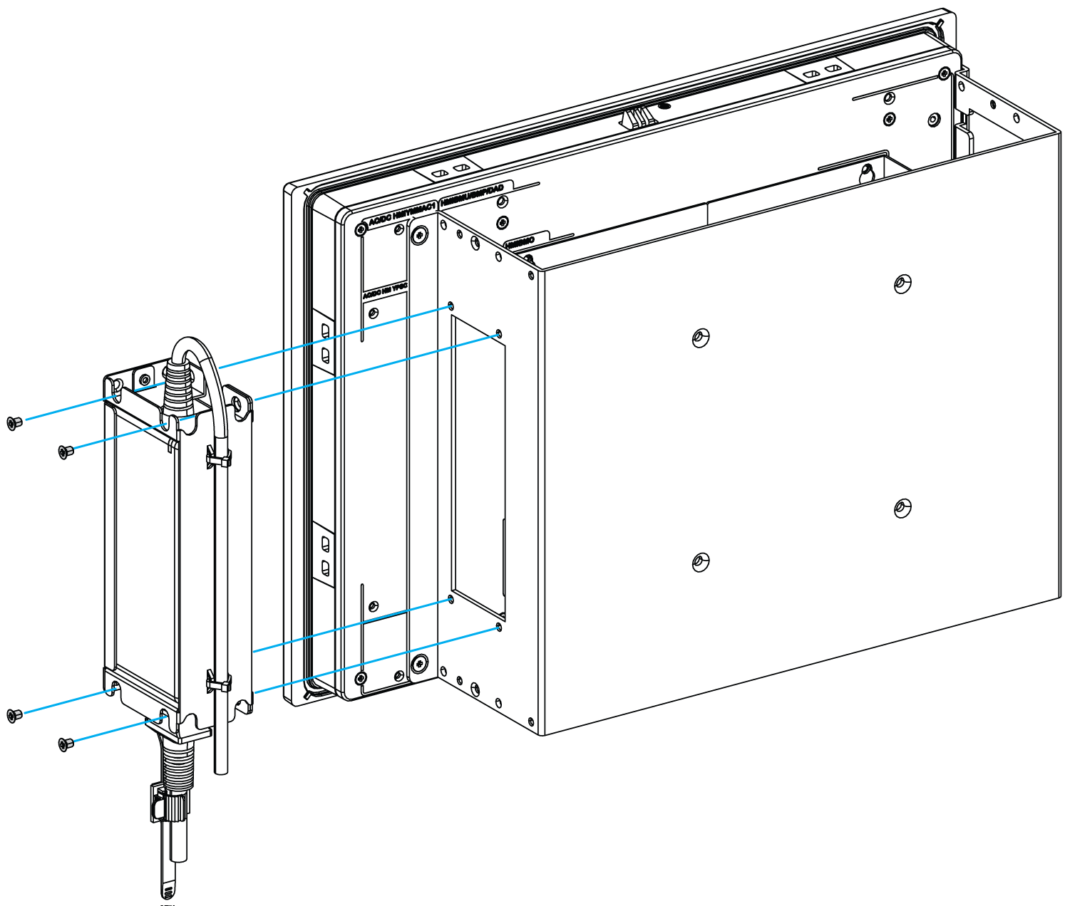
NOTE: The recommended torque to tighten these screws is 0.5 Nm (4.5 lb-in). |
|
3 |
Remove the terminal block from the power connector on the Box and connect the power cord to the terminal block: 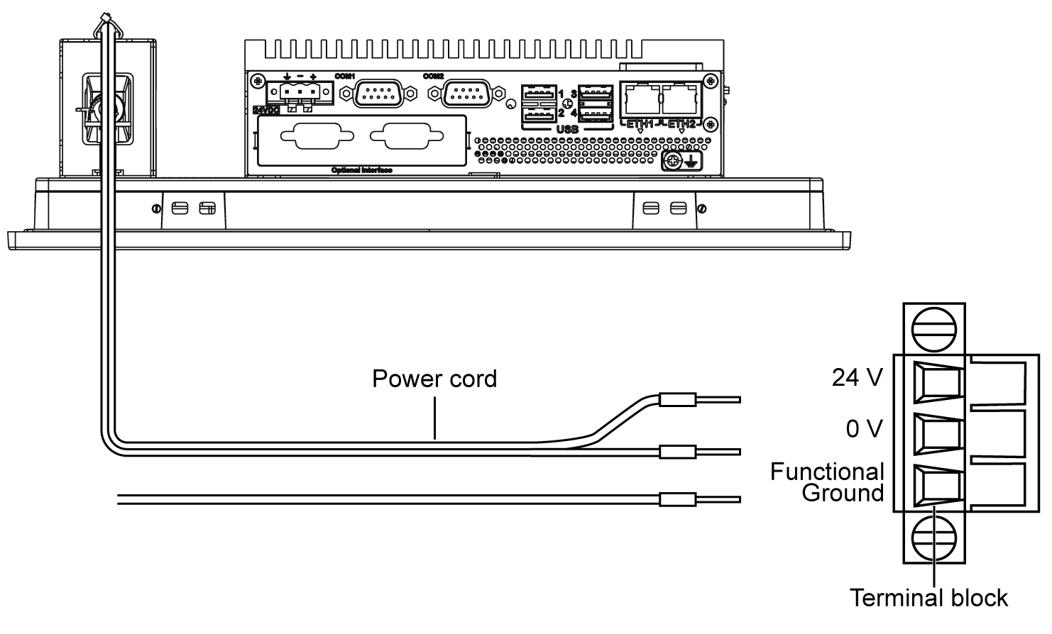
Connect the black wire with the 0 V and the red wire with the 24 V of the terminal block. Use 2.5 mm2 copper wire to make the ground connection of the terminal block. |
|
4 |
Place the terminal block in the power connector and tighten the screws: 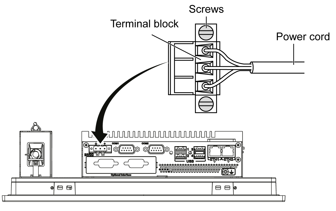
NOTE: The recommended torque to tighten these screws is 0.5 Nm (4.5 lb-in). |
|
5 |
Put on the clip through the mounting bracket and the power cord together: 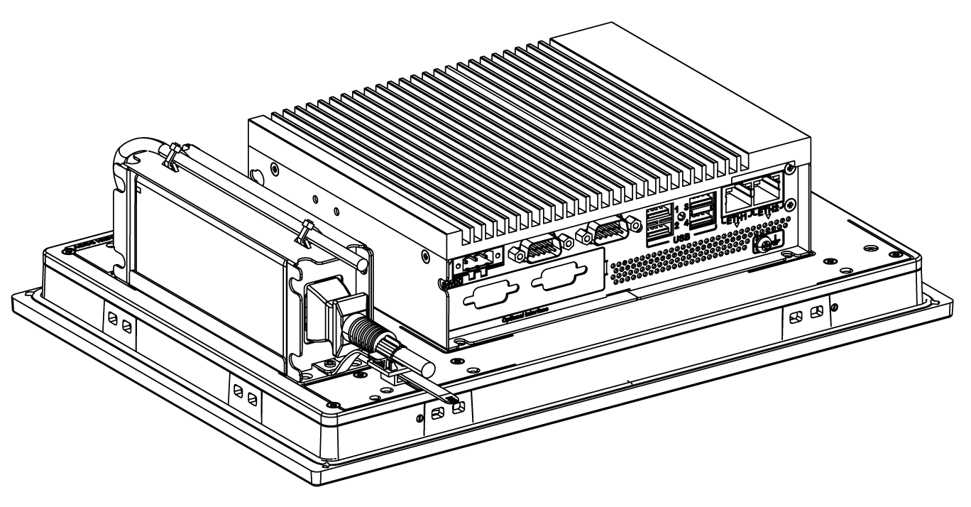
Press the clip to fasten the power cord: 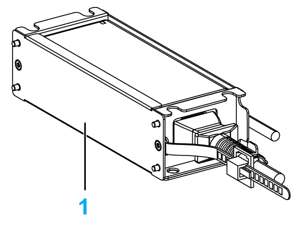
1 Mounting bracket |
|
6 |
Connect the AC power cable of the AC power supply module from its power source. |