FB_Drive_PosControl - General Information
Task
This function block allows for position control of a velocity-controlled drive with position feedback through an encoder. Usually, the motion controller provides the target position for a position-controlled movement. The control loops in the servo drive are then in charge of position control (as well as current control and velocity control) for the movement. This function block allows you to operate a velocity-controlled drive such as a variable speed drive using position control through the logic/motion controller, not by the drive itself (that may not provide the required position control functionality).
Description
Overview
The function block uses a virtual axis of the type MOIN.FB_ControlledAxis as its input. A position-controlled movement of this virtual axis (for example, using the function block MC_MoveAbsolute or the function block MC_MoveRelative) provides the actual position (as determined by the encoder) of the movement using the input i_diActualPosition.
Based on this position input and the scaling parameters of the encoder (inputs i_diIncrementalResolution and i_lrPositionResolution), the function block FB_Drive_PosControl calculates the output velocity for the drive in RPM (output q_diSetVelocity) or in user-defined units for every second (output q_lrSetVelocity) as reference values for the movement to the target position.
The profile generator follows the PLCopen standard in generating the position values.
Axis Type
The axis at the input i_ifAxis has to be of the type MOIN.FB_ControlledAxis. The axis has to be a virtual axis; that is, it is not connected to a drive. If the axis at the input i_ifAxis is not of the type MOIN.FB_ControlledAxis, an error is detected (ET_Result is set to OnlyControlledAxisSupported). If the axis at the input i_ifAxis is of the type MOIN.FB_ControlledAxis, but it is not a virtual axis (that is, it is connected to a drive), an error is detected (ET_Result is set to ControlledAxisIsConnectedToDevice).
Control Loop
Representation of the control loop:
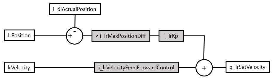
-
Items with a gray background are parameters that determine the control performance.
-
Items with a leading “i_” are inputs of the function block FB_Drive_PosControl.
-
Items with a leading “q_” are outputs of the function block FB_Drive_PosControl.
-
lrPosition is the target position for the movement.
-
lrVelocity is the input velocity from the application.
-
i_diActualPosition is the actual position as determined by the encoder.
-
i_lrMaxPositionDiff is the position deviation. Position deviation is the difference between the reference position (lrPosition of the virtual axis) and the actual position of the drive at the input i_diActualPosition as determined by the encoder.
-
i_lrKp is the proportional gain. The proportional gain of the control loop reduces the position deviation. The proportional gain is a reactive correction intended to reduce the position deviation that has already occurred.
-
i_VelocityFeedForwardControl is the velocity feed-forward gain. The velocity feed-forward gain is a proactive correction to reduce predictable overshoot or further minimize the position deviation during the constant velocity portion of the movement.
The control loop is typically tuned in the following sequence:
-
Position deviation
-
Proportional gain
-
Velocity feed-forward
Since the factors determining the control performance are interdependent, and since the required control performance hinges on the application, you may have to increase or decrease individual values and determine the effects by performing tests. The appropriate values for the inputs determining the control performance depend on your application. Factors include, for example, drive, motor, load, inertia and friction. Determine the values that provide an appropriate control performance for your application experimentally, for example, using an oscilloscope and traces during tests.
Tuning control loop parameters is a process of approximation to the required values. It involves comprehensive tests of the application, including the physical components, during development and/or commissioning.
| WARNING | |
|---|---|
Control Loop Tuning through Position Deviation Monitoring
Position deviation is the difference between the reference position (lrPosition of the virtual axis) and the position of the drive at the input i_diActualPosition as determined by the encoder. It is a measure of the ability of the drive to follow the reference positions during the movement to the target position. If the drive can no longer follow the reference positions because the position deviation is greater than the value set through the input i_lrMaxPositionDiff, a position deviation error is detected (also referred to as “following error”, for example, by PLCopen, or as “tracking error”). The less the position deviation, the more responsive and stiff the control system. However, in a closed-loop system with position feedback, a certain amount of position deviation is a physical necessity.
The maximum difference between the reference position and the position is set by the input i_lrMaxPositionDiff. If the position deviation exceeds this value, an error is detected (PositionDiffOutOfRange) and the virtual axis transitions to the operating state ErrorStop. A negative value at this input disables position deviation monitoring.
| WARNING | |
|---|---|
The appropriate value for the maximum position deviation i_lrMaxPositionDiff depends on your application. Factors include, for example, drive, motor, load, and friction. Determine the value that provides an appropriate control performance for your application experimentally, for example, using an oscilloscope and traces during tests. The property lrActualPositionDifference of the function block allows you to read the position deviation.
Determine the maximum position deviation value i_lrMaxPositionDiff before you proceed with tuning the proportional gain Kp and the velocity feed-forward.
Control Loop Tuning through Proportional Gain
The proportional gain Kp of the control loop reduces the position deviation. It is directly proportional to the amount of position deviation. This means that the value of the position deviation is multiplied by the proportional gain to determine a velocity output value that reduces the position deviation. The higher the proportional gain, the more responsive the controller. However, the higher the proportional gain, the higher the likelihood of oscillations (continuous acceleration and deceleration).
Excessively high proportional gain values can result in velocity oscillations (continuous variations between acceleration and deceleration) and consequential unintended movements.
| WARNING | |
|---|---|
Determining the appropriate value for the proportional gain i_lrKp:
|
Step |
Action |
|---|---|
|
1 |
Test the control performance with the default value for the proportional gain Kp at the input i_lrKp and observe the velocity value at the corresponding outputs under the intended operating conditions. |
|
2 |
If no fluctuations of the velocity value, that means that, no oscillations in the form of continuous acceleration and deceleration can be observed, increase the proportional gain value Kp by a small increment to trigger a step response, and repeat the control performance test. |
|
3 |
Repeat the increase in the proportional gain value Kp in small increments to trigger a step response, and repeat the subsequent control performance tests after each increase until fluctuations of the velocity value (oscillations) can be observed . |
|
4 |
As soon as fluctuations of the velocity value (oscillations) can be observed with a given value for the proportional gain Kp, reduce the value for the proportional gain Kp by 10 %. Result: You have determined the maximum value for value for the proportional gain Kp. |
Control Loop Tuning through Velocity Feed-Forward
The velocity feed-forward gain is a proactive correction to reduce predictable overshoot and further minimize the position deviation during the constant velocity portion of the movement. Overshoot is the extent to which the actual velocity value is “ahead” of the reference value. Reducing the value reduces the overshoot, in particular, towards the end of the movement.
Dead Time Compensation
The input i_uiDeadTime allows for dead time compensation. The input lets you specify the number of function block calls by which the position reference value (lrPosition of the virtual axis) is delayed for the calculation of the position deviation. To determine the correct value for this input, determine the time delay between the reference position and the actual position. Divide this value by the time interval of the task in which the function block is cyclically called. Example: The time delay between the reference position and the actual position is 110 ms. The time interval of the task in which FB_Drive_PosControl is called is 10 ms. The appropriate value for i_uiDeadTime is 11 (110/10).
Detected Errors and Operating State Transitions of the Drive
The inputs i_xExternalError and i_xDriveEnabled allow you to respond to detected drive errors and manage the transition to and from the operating state Operation Enabled of the drive.
Interface
|
Input |
Data type |
Description |
|---|---|---|
|
i_ifAxis |
MOIN.IF_Axis |
Reference to the axis for which the function block is to be executed. |
|
i_xEnable |
BOOL |
Starts (value TRUE) or terminates (value FALSE) the execution of the function block. |
|
i_diActualPosition |
DINT |
The value at this input is the actual position of the drive as determined by the encoder. |
|
i_lrKp |
LREAL |
Value range: Positive LREAL value and 0 Default value: 0 The value at this input specifies the proportional gain Kp of the control loop. |
|
i_uiDeadTime |
UINT |
Value range: 0 ... 50 Default value: 0 The value at this input specifies the setting for dead time compensation in the form of number of function block calls by which the position reference value (lrPosition of the virtual axis) is delayed for the calculation of the position deviation. |
|
i_lrMaxPositionDiff |
LREAL |
Value range: LREAL value Default value: 0 The value at this input determines the maximum position deviation for position deviation monitoring. The position deviation is the difference between the reference position (lrPosition of the virtual axis at the input i_ifAxis) and the actual position (at the input i_diActualPosition) of the drive as determined by the encoder. A positive value starts position deviation monitoring with the specified value. A negative value disables position deviation monitoring. If the position deviation value exceeds the value at this input, the error PositionDiffOutOfRange is detected. As long as the value at this input is 0, the error InvalidPositionDiff is detected. |
|
i_lrMaxVelocity |
LREAL |
Value range: LREAL value Default value: 0 The value at this input specifies the maximum velocity for the movement in user-defined units. Use a positive value for positive direction of movement, or a negative value for negative direction of movement. |
|
i_lrMinVelocity |
LREAL |
Value range: LREAL value Default value: 0 The value at this input specifies the minimum velocity for the movement in user-defined units. Use a positive value for positive direction of movement, or a negative value for negative direction of movement. |
|
i_lrVelocityFeedForwardControl |
LREAL |
Value range: 0 ... 1 Default value: 1 The value at this input specifies the velocity feed-forward. |
|
i_diIncrementalResolution |
DINT |
Value range: Positive integer value greater than 1 The value at this input specifies the encoder resolution in increments (number of increments for every revolution). |
|
i_lrPositionResolution |
LREAL |
Value range: Positive integer value greater than 1 The value at this input specifies the encoder resolution in user-defined units (number of user-defined for every revolution). |
|
i_xInvertDirection |
BOOL |
Value range: FALSE, TRUE Default value: FALSE The value at this input is used for scaling the encoder reading by i_diActualPosition.
|
|
i_xExternalError |
BOOL |
Value range: TRUE, FALSE Default value: FALSE The value at this input indicates whether an external error, for example, a drive error, has been detected. This allows you to respond to detected drive errors. If the value is TRUE, the error ExternalError is detected. To reset the detected error caused by this input, set the value at the input i_xEnable to FALSE and then to TRUE. |
|
i_xDriveEnabled |
BOOL |
Value range: TRUE, FALSE Default value: FALSE If this input is set to FALSE and the value at the input i_xEnable is TRUE, the reference position is updated according to the modifications in the encoder reading at the input i_diActualPosition. This means that lrPosition of i_ifAxis has the same value as the property lrActualPosition, and the value of the property lrActualPositionDifference is zero. If the drive is disabled (that is, if it is not in the operating state Operation Enabled), the output q_xError is set to FALSE and the value at the output q_etResult is set to DriveNotEnabled. If the value at this input is TRUE, the movement is controlled according to the control loop parameters set. The position of the virtual axis is not affected when the value is TRUE. |
|
Output |
Data type |
Description |
|---|---|---|
|
q_lrSetVelocity |
LREAL |
The value at this output specifies the reference velocity for the drive in user-defined units. |
|
q_diSetVelocity |
DINT |
The value at this output specifies the reference velocity for the drive in RPM. |
|
q_xActive |
BOOL |
Value range: FALSE, TRUE Default value: FALSE
|
|
q_xError |
BOOL |
Indicates whether the last execution of the function block was successful (value FALSE = no error detected) or not (value TRUE = error detected). |
|
q_etResult |
Provides information on the execution of the function block. |
Properties
|
Name |
Data type |
Access |
Description |
|---|---|---|---|
|
lrActualPosition |
LREAL |
Read |
Returns the actual position of the drive (i_diActualPosition) in user-defined units. If MC_SetPosition is executed for the virtual axis at the input i_ifAxis, this property provides the corresponding value. |
|
lrActualPositionDifference |
LREAL |
Read |
Returns the position deviation between reference position and actual position of the drive in user-defined units. |
|
lrErrorStopDeceleration |
LREAL |
Read/Write |
Returns or writes the deceleration value for a stop after an error has been detected (value at ET_Result is ErrorStopping). |