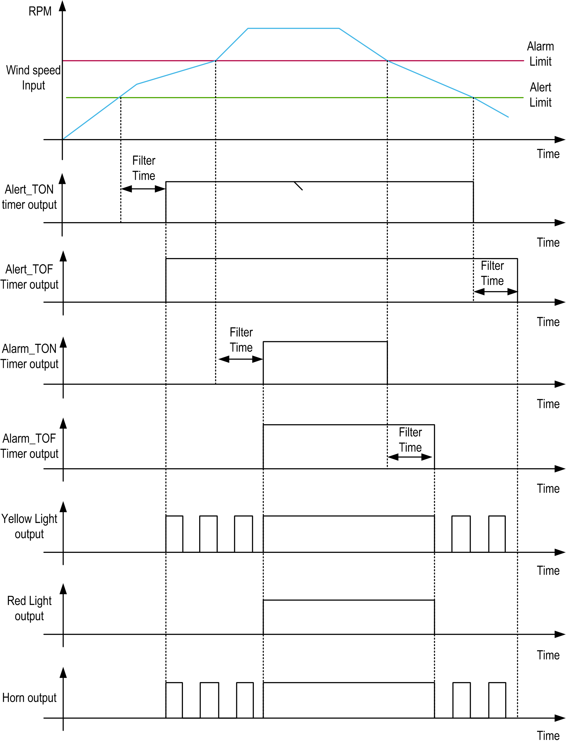
The Wind speed control function is designed to:
oProvide an alert indication (after filter time) when the wind speed is greater than the set alert threshold. In this case, a blinking yellow light and a pulsed horn are generated.
oProvide an alarm indication (after filter time) when the wind speed is greater than the set alarm threshold. In this case, a continuous red and yellow light and a constant horn signal are generated.
oProvide a test to check the indicator lights.
oProvide an alarm if no signal from the anemometer is detected within a period of 8 hours.
oIf an alarm is indicated and the wind speed drops below the alarm limit , or an alert is indicated and the wind speed drops below the alert limit, apply the filter time delay before the alarm/alert is withdrawn.
oStore the last 11 alarm events in a FIFO data array (0 to 10), which can be accessed through the q_adtDttmAlrm output pin, where position 0 represents the most recent alarm event.
The following figure represents the timing and signals diagram for WindSpeedCtrl function block.
