Cabling the VRKP•S0•NC
|
Step |
Action |
|---|---|
|
1 |
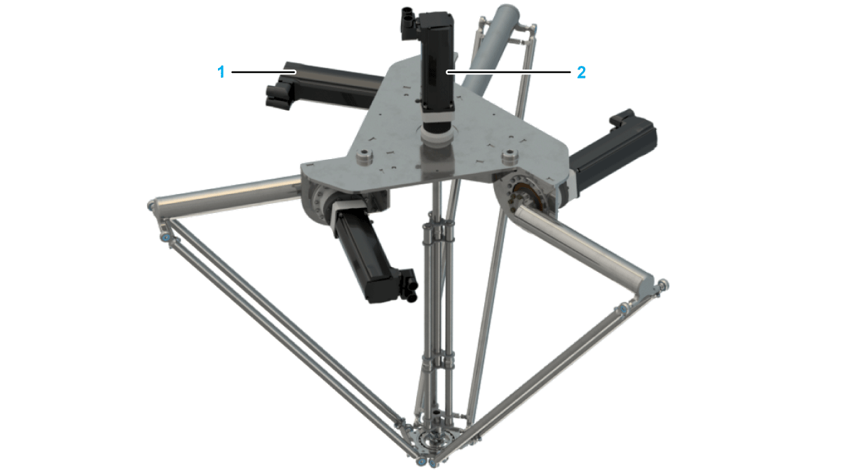
Feed the three encoder cables (four with VRKP0S0R / VRKP1S0R / VRKP2S0R / VRKP4S0R / VRKP5S0R / VRKP6S0R (2)) directly to the motors (1). 
For robots with a motorized module: Cable the motorized module according to the cabling instructions of the respective module: |
|
2 |
Feed the three power cables (four with VRKP0S0R / VRKP1S0R / VRKP2S0R / VRKP4S0R / VRKP5S0R / VRKP6S0R) directly to the motors.
NOTE: For equipment that you are supplying that is not described in the present document, consult the documentation for those products.
|
|
3 |
Attach the encoder and the power cables as described in the SH3 Servo motor Motor Manual and the MH3 Servo motor Motor Manual. |
|
4 |
Couple the DC buses of the servo amplifiers so that braking motors can feed back their power to the accelerating motors in the case of an on-path stop of the robot. Due to the coupling of the DC buses, the existing energy suffices in many cases for an on-path stop of the robot. In case of a power outage of the 24 Vdc supply this backfeeding measure does not have any effect. For more information, see Lexium 52 Hardware Guide or Lexium 62 Hardware Guide.
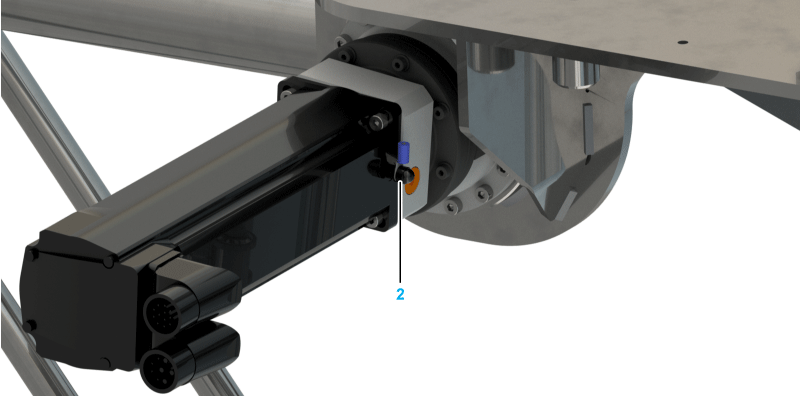
NOTE: When routing the cables, ensure that the grounding cap (2) remains on the ground connection of the motors. The motor supply cable may become damaged by the thread of the ground strap attachment.

|
|
5 |
Verify the correct routing and fastening of the cables to help prevent any collision of cables and moving parts. |
| DANGER | |
|---|---|
| DANGER | |
|---|---|
| NOTICE | |
|---|---|