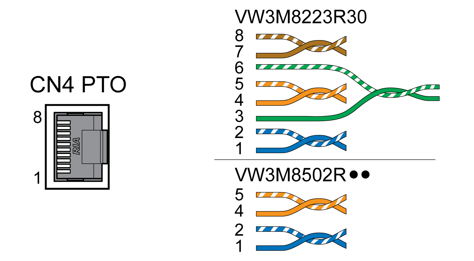
Connection PTO (CN4, Pulse Train Out)
General
5 V signals are available at the PTO (Pulse Train Out, CN4) output. Depending on parameter PTO_mode, these signals are ESIM signals (encoder simulation) or logically fed through PTI input signals (P/D signals, A/B signals, CW/CCW signals). The PTO output signals can be used as PTI input signals for another drive. The signal level corresponds to RS422, see Output PTO (CN4). The PTO output supplies 5 V signals, even if the PTI input signal is a 24 V signal.
Cable Specifications
|
Shield: |
Required, both ends grounded |
|
Twisted Pair: |
Required |
|
PELV: |
Required |
|
Cable composition: |
8 * 0.14 mm2 (8 * AWG 24) |
|
Maximum cable length: |
100 m (328 ft) |
Use pre-assembled cables to reduce the risk of wiring errors, see Accessories and Spare Parts.
Wiring Diagram
Wiring diagram Pulse Train Out (PTO)

|
Pin |
Signal |
Pair |
Meaning |
|---|---|---|---|
|
1 |
ESIM_A |
2 |
ESIM channel A |
|
2 |
ESIM_A |
2 |
ESIM channel A, inverted |
|
4 |
ESIM_B |
1 |
ESIM channel B |
|
5 |
ESIM_B |
1 |
ESIM channel B, inverted |
|
3 |
ESIM_I |
3 |
ESIM index pulse |
|
6 |
ESIM_I |
3 |
ESIM index pulse, inverted |
|
7 |
PTO_0V |
4 |
Reference potential |
|
8 |
PTO_0V |
4 |
Reference potential |