Holding Brake (Option)
Holding Brake
The holding brake in the motor has the task of holding the motor position when the power stage is disabled. The holding brake is not a safety function and not a service brake.
| WARNING | |
|---|---|
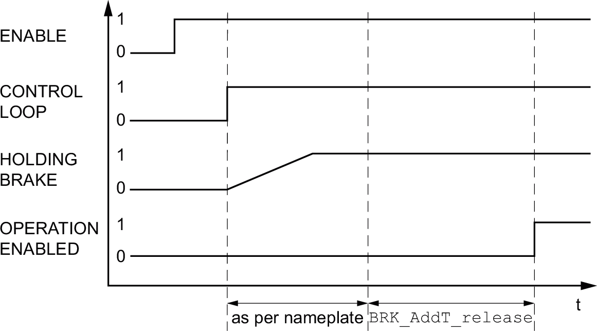
Releasing the Holding Brake
When the power stage is enabled, current is applied to the motor. When current is applied to the motor, the holding brake is automatically released.
Releasing the holding brake requires a certain amount of time. This time is contained in the electronic nameplate of the motor. Transition to the operating state 6 Operation Enabled is only possible after this time delay has elapsed.
An additional time delay can be set via parameters, see Additional Time Delay for Releasing the Holding Brake.
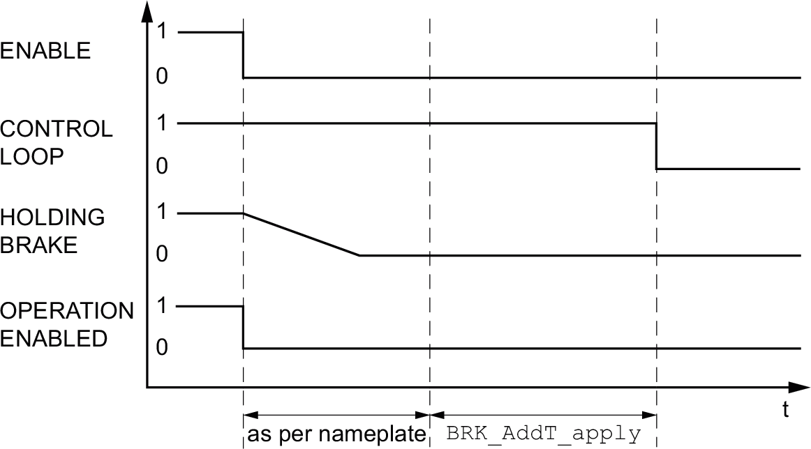
Applying the Holding Brake
When the power stage is disabled, the holding brake is automatically applied.
However, applying the holding brake requires a certain amount of time. This time is contained in the electronic nameplate of the motor. Current remains to be applied to the motor during this time delay.
See section Functional Safety for additional information on the behavior of the holding brake when the safety function STO is triggered.
An additional time delay can be set via parameters, see Additional Time Delay for Applying the Holding Brake.
Additional Time Delay for Releasing the Holding Brake
An additional time delay can be set via the parameter BRK_AddT_release.
Transition to the operating state 6 Operation Enabled is only possible after the entire time delay has elapsed.
|
Parameter name HMI menu HMI name |
Description |
Unit Minimum value Factory setting Maximum value |
Data type R/W Persistent Expert |
Parameter address via fieldbus |
|---|---|---|---|---|
|
Additional time delay for releasing the holding brake. The overall time delay for releasing the holding brake is the time delay from the electronic nameplate of the motor and the additional time delay in this parameter. Type: Signed decimal - 2 bytes Write access via Sercos: CP2, CP3, CP4 Setting can only be modified if power stage is disabled. Modified settings become active the next time the power stage is enabled. |
ms 0 0 400 |
INT16 R/W per. - |
Modbus 1294 IDN P-0-3005.0.7 |
Additional Time Delay for Applying the Holding Brake
An additional time delay can be set via the parameter BRK_AddT_apply.
Current continues to be applied to the motor until the entire time delay has passed.
|
Parameter name HMI menu HMI name |
Description |
Unit Minimum value Factory setting Maximum value |
Data type R/W Persistent Expert |
Parameter address via fieldbus |
|---|---|---|---|---|
|
Additional time delay for applying the holding brake. The overall time delay for applying the holding brake is the time delay from the electronic nameplate of the motor and the additional time delay in this parameter. Type: Signed decimal - 2 bytes Write access via Sercos: CP2, CP3, CP4 Setting can only be modified if power stage is disabled. Modified settings become active the next time the power stage is enabled. |
ms 0 0 1000 |
INT16 R/W per. - |
Modbus 1296 IDN P-0-3005.0.8 |
Verifying the Function of the Holding Brake
The device is in the operating state 4 Ready To Switch On.
|
Step |
Action |
|---|---|
|
1 |
Start the operating mode Jog (HMI: (op)→(JOg)→(JGST)). The power stage is enabled and the holding brake released. The HMI displays (JG-). |
|
2 |
If the holding brake has been released, hold down the navigation button. Then press ESC. As long as the navigation button is held down, the motor moves. When you press ESC, the holding brake is applied again and the power stage is disabled. |
|
3 |
If the holding brake is not released, press ESC. When you press ESC, the power stage is disabled. |
|
4 |
Verify the wiring if the behavior of the holding brake is not correct. |
Releasing the Holding Brake Manually
Mechanical adjustments may require you to manually rotate the motor shaft.
Manual release of the holding brake is only possible in the operating states 3 Switch On Disabled, 4 Ready To Switch On or 9 Fault.
When the product is operated for the first time, there is a risk of unanticipated movements caused by, for example, incorrect wiring or unsuitable parameter settings. Releasing the holding brake can cause an unintended movement, for example, a falling load in the case of vertical axes.
| WARNING | |
|---|---|
Applying the Holding Brake Manually
For testing the holding brake, you may want to manually apply the holding brake.
You can only apply the holding brake manually when the motor is at a standstill.
If you enable the power stage after the holding brake has been applied manually, the holding brake remains applied.
Manual application of the holding brake has priority over automatic and manual release of the holding brake.
If a movement is started after the holding brake has been applied manually, this can cause wear.
| NOTICE | |
|---|---|
As of firmware version ≥V01.04, you can manually apply the holding brake.
Releasing the Holding Brake Manually via a Signal Input
In order to release the holding brake via a signal input, you must first parameterize the signal input function "Release Holding Brake", see Digital Signal Inputs and Digital Signal Outputs.
Releasing or Applying the Holding Brake Manually via the Fieldbus
The parameter BRK_release can be used to release the holding brake via the fieldbus.
|
Parameter name HMI menu HMI name |
Description |
Unit Minimum value Factory setting Maximum value |
Data type R/W Persistent Expert |
Parameter address via fieldbus |
|---|---|---|---|---|
|
Manual operation of the holding brake. 0 / Automatic: Automatic processing 1 / Manual Release: Manual release of holding brake 2 / Manual Application: Manual applying of holding brake You can apply or release the holding brake manually. The holding brake can only be manually released in the operating states 'Switch On Disabled', 'Ready To Switch On' or 'Fault'. If you have applied the holding brake manually and then want to release it manually, you must first set this parameter to Automatic and then to Manual Release. Type: Unsigned decimal - 2 bytes Write access via Sercos: CP2, CP3, CP4 Modified settings become active immediately. |
- 0 0 2 |
UINT16 R/W - - |
Modbus 2068 IDN P-0-3008.0.10 |