Input PTI (CN5)
Description
5 V signals or 24 V signals can be connected to the PTI (Pulse Train In) input.
The following signals can be connected:
-
A/B signals (ENC_A/ENC_B)
-
P/D signals (PULSE/DIR)
-
CW/CCW signals (CW/CCW)
Input Circuit and Selection of Method
The input circuit and the selected method affect the maximum permissible input frequency and the maximum permissible line length:
|
Input circuit |
RS422 |
Push pull |
Open collector |
|
|---|---|---|---|---|
|
Minimum input frequency with method position synchronization |
Hz |
0 |
0 |
0 |
|
Minimum input frequency with method velocity synchronization |
Hz |
100 |
100 |
100 |
|
Maximum input frequency |
MHz |
1 |
0.2 |
0.01 |
|
Maximum line length |
m (ft) |
100 (328) |
10 (32.8) |
1 (3.28) |
Signal input circuits: RS422, Push Pull and Open Collector
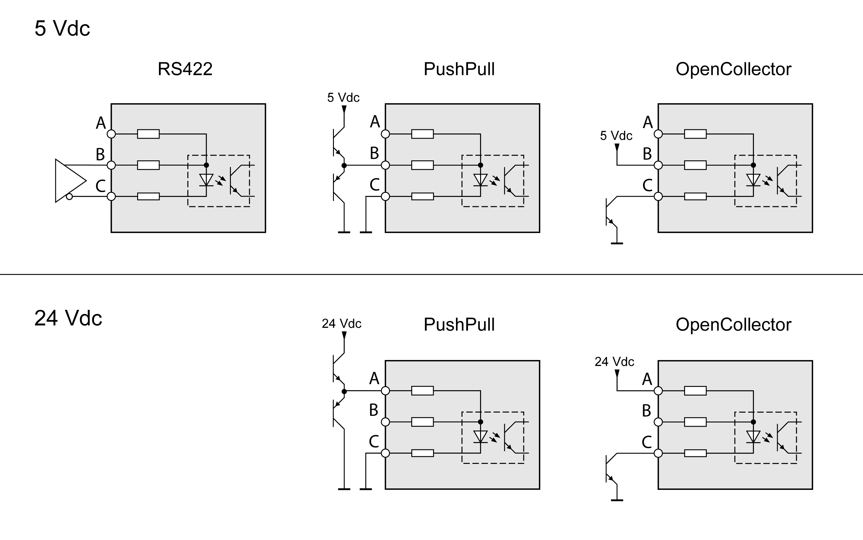
|
Input |
Pin(1) |
RS422(2) |
5V |
24V |
|---|---|---|---|---|
|
A |
Pin 7 |
Reserved |
Reserved |
PULSE(24V) ENC_A(24V) CW(24V) |
|
Pin 8 |
Reserved |
Reserved |
DIR(24V) ENC_B(24V) CCW(24V) |
|
|
B |
Pin 1 |
PULSE(5V) ENC_A(5V) CW(5V) |
PULSE(5V) ENC_A(5V) CW(5V) |
Reserved |
|
Pin4 |
DIR(5V) ENC_B(5V) CCW(5V) |
DIR(5V) ENC_B(5V) CCW(5V) |
Reserved |
|
|
C |
Pin 2 |
PULSE ENC_A CW |
PULSE ENC_A CW |
PULSE ENC_A CW |
|
Pin 5 |
DIR ENC_B CCW |
DIR ENC_B CCW |
DIR ENC_B CCW |
|
|
(1) Observe the different pairing in the case of twisted pair: Pin 1 / pin 2 and pin 4 / pin 5 for RS422 and 5V pin 7 / pin 2 and pin 8 / pin 5 for 24V (2) Due to the input current of the optocoupler in the input circuit, a parallel connection of a driver output to several devices is not permitted. |
||||
Function A/B Signals
External A/B signals can be counted at the PTI input.
|
Signal |
Value |
Function |
|---|---|---|
|
Signal A before signal B |
0 -> 1 |
Count in positive direction |
|
Signal B before signal A |
0 -> 1 |
Count in negative direction |
Time chart with A/B signal, counting forwards and backwards
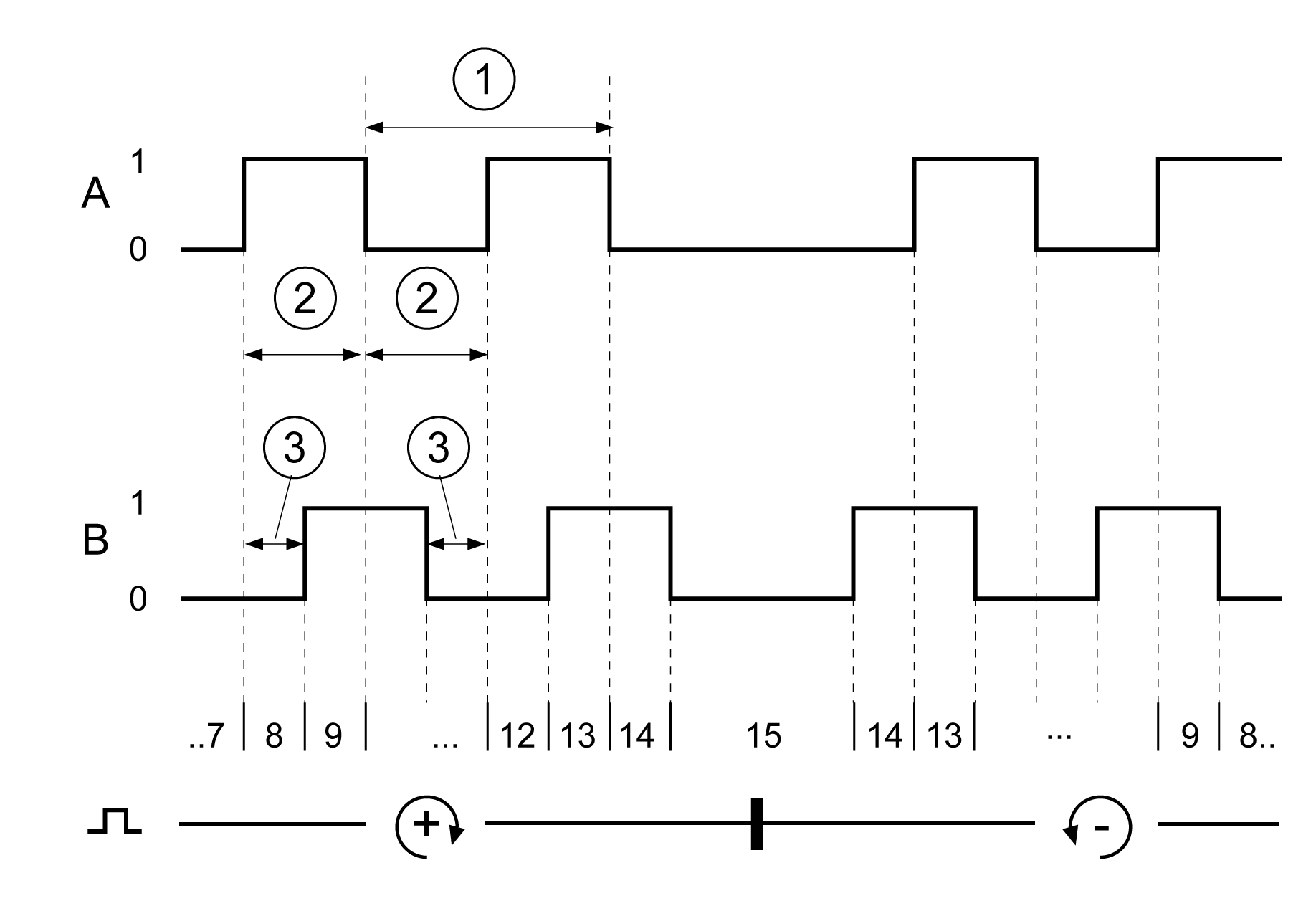
|
Times for pulse/direction |
Minimum value |
|---|---|
|
(1) Cycle duration A, B |
1 μs |
|
(2) Pulse duration |
0.4 μs |
|
(3) Lead time (A, B) |
200 ns |
Function P/D Signals
External P/D signals can be counted at the PTI input.
|
Signal |
Value |
Function |
|---|---|---|
|
PULSE DIR |
0 -> 1 0 / open |
Count in positive direction |
|
PULSE DIR |
0 -> 1 1 |
Count in negative direction |
Time chart with pulse/direction signal
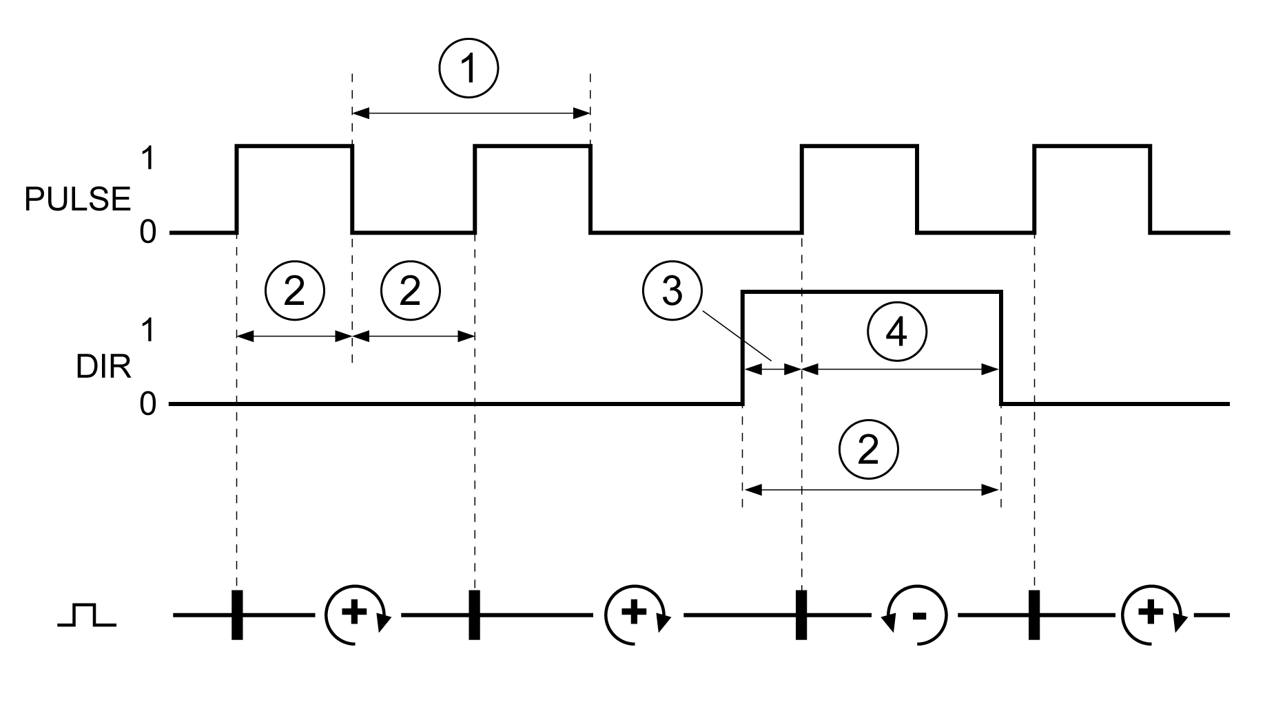
|
Times for pulse/direction |
Minimum value |
|---|---|
|
(1) Cycle duration (pulse) |
1 μs |
|
(2) Pulse duration (pulse) |
0.4 μs |
|
(3) Lead time (Dir-Pulse) |
0 μs |
|
(4) Hold time (Pulse-Dir) |
0.4 μs |
Function CW/CCW Signals
External CW/CCW signals can be counted at the PTI input.
|
Signal |
Value |
Function |
|---|---|---|
|
CW |
0 -> 1 |
Count in positive direction |
|
CCW |
0 -> 1 |
Count in negative direction |
Time chart with "CW/CCW"
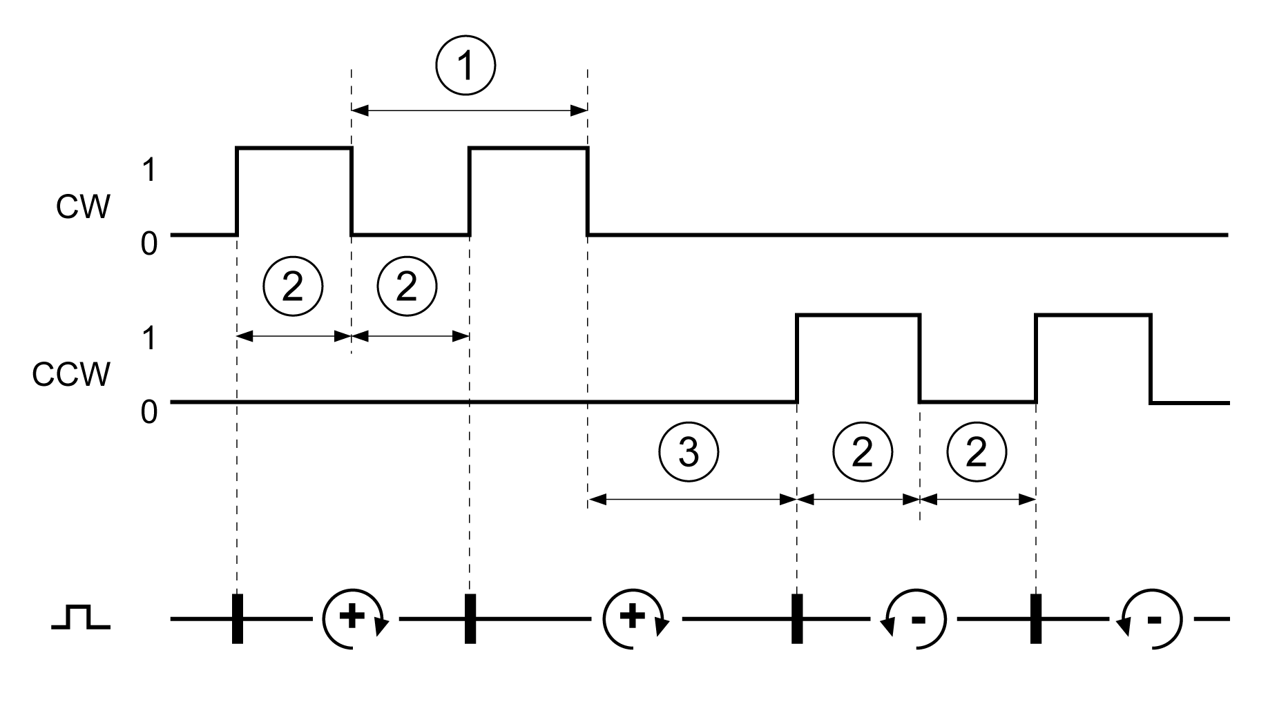
|
Times for pulse/direction |
Minimum value |
|---|---|
|
(1) Cycle duration CW, CCW |
1 μs |
|
(2) Pulse duration |
0.4 μs |
|
(3) Lead time (CW-CCW, CCW-CW) |
0 μs |