Installing and Removing Modules
Overview
Many components of the equipment, including the printed circuit board, operate with mains voltage, or present transformed high currents, and/or high voltages.
The motor itself generates voltage when the motor shaft is rotated.
| DANGER | |
|---|---|
Electrostatic discharge (ESD) may permanently damage the module either immediately or over time.
| NOTICE | |
|---|---|
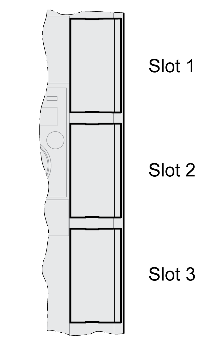
The drive has 3 module slots:

The module slots are designed for the following modules:
|
Slot |
Module |
|---|---|
|
Slot 1 |
Safety module eSM |
|
Slot 2 |
Encoder module RSR (resolver interface) Encoder module DIG (digital interface) Encoder module ANA (analog interface) |
|
Slot 3 |
Fieldbus module Sercos III |
Inserting a Module Into a Slot
Disconnect all power (power stage supply and 24 Vdc control supply) before inserting or removing a module.
Procedure for inserting a module:
|
Step |
Action |
|---|---|
|
1 |
Fully read and understand the drive user guide as well as the user guide for the module prior to installing the module. |
|
2 |
Verify that the order number on the nameplate of the module corresponds to the specification in the manual for the module. |
|
3 |
Note and record the serial number, revision and DOM shown on the nameplate of the module and the nameplate of the device. |
|
4 |
Remove the cover from the module slot and keep the cover. |
|
5 |
Inspect the module for visible damage. Do not install damaged modules. |
|
6 |
Push the module into the appropriate slot until the snap-in lock snaps in. |
Information on wiring can be found in the section "Installation" of the user guide for the module.
Fasten the connection cable to the cable guide of the device.
Various settings must be made the next time the drive is powered on. See the section "Commissioning" of the user guide for the module for details on these settings.
Removing a Module From a Slot

Disconnect all power (power stage supply and 24 Vdc control supply) before inserting or removing a module.
Procedure for removing a module from a slot of the device:
-
Label the connection cables. Remove the wiring of the module.
-
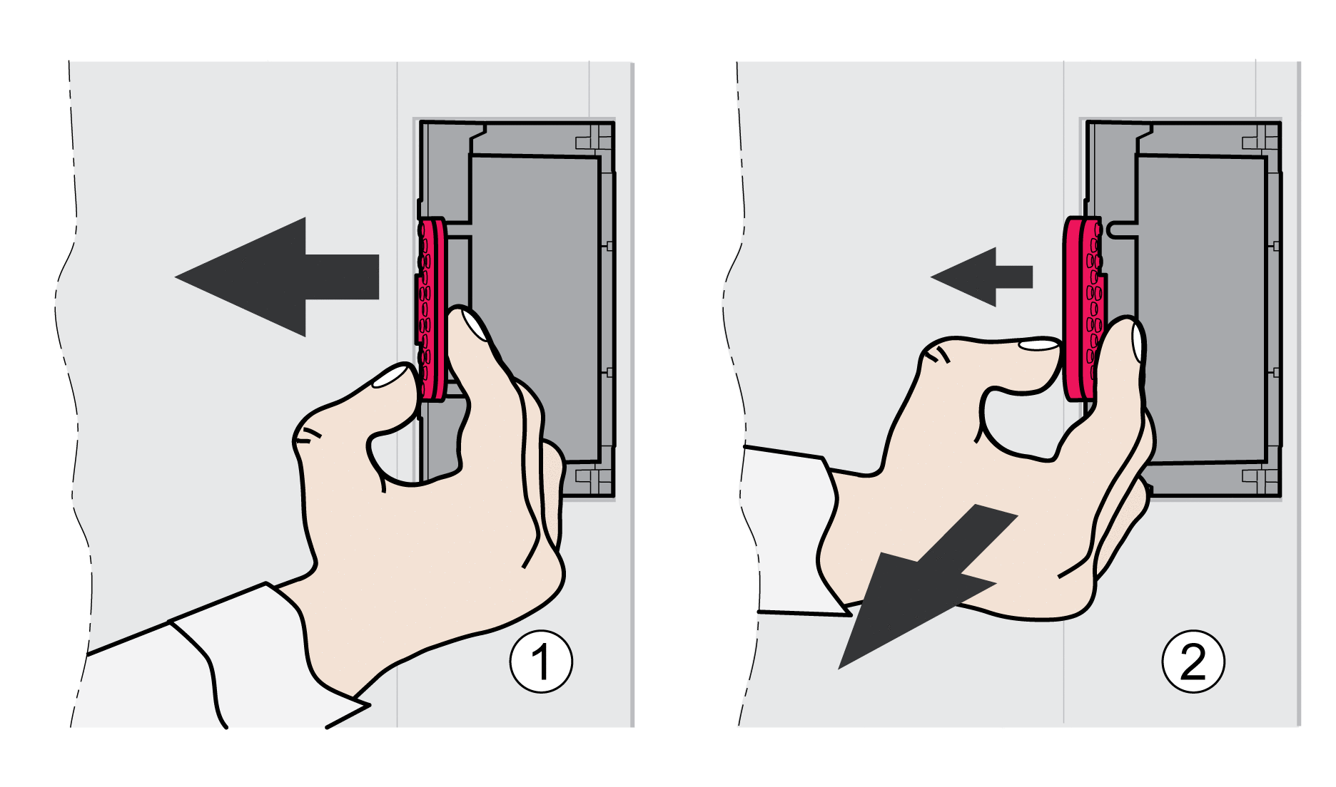
Push the snap-in lock of the module to the left (1) and pull out the module at the snap-in lock (2) while holding it to the left.
-
Close the module slot with the cover.
The next time the drive is powered on, it will signal a module replacement. See section Acknowledging a Module Replacement for additional information.