Connecting the Connection Module to the Track
Wiring Example
Also refer to Additional Wiring Examples.
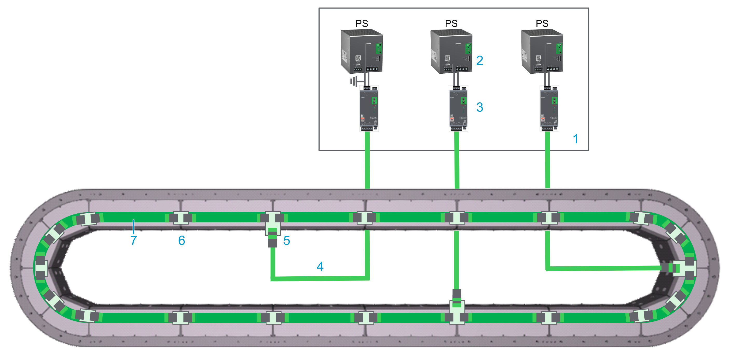
Closed track
|
Element |
Description |
|---|---|
|
1 |
Control cabinet |
|
2 |
Power supply |
|
3 |
Lexium™ MC connection module |
|
4 |
Lexium™ MC power cable with socket connector |
|
5 |
Lexium™ MC power interconnect with plug connector |
|
6 |
Lexium™ MC power interconnect without connector |
|
7 |
Internal DC bus connection |
Description
-
The Lexium™ MC12 multi carrier track is connected to the Lexium™ MC connection module with pre-assembled cables.
NOTE: The front covers of the segments are not connected to the PE (protective ground/earth). The electrical safety requirements are fulfilled by appropriate insulation measures (protective separation). -
The Lexium™ MC connection module supplies the Lexium™ MC12 multi carrier track with power (DC bus).
The Lexium™ MC connection module limits the DC bus voltage to <60 Vdc, conforming to Functional Safety rules. Refer to Scope of Operation (Designated Safety Function).
-
The DC bus (up to 60 A) in the Lexium™ MC12 multi carrier track is distributed from segment to segment via the Lexium™ MC power interconnects.
-
The Lexium™ MC12 multi carrier requires that the power supply must be dimensioned according to the number of segments, segment groups, carriers, load and other pertinent parameters.
The maximum number of 24 segments per power supply/Lexium™ MC connection module combination must not be exceeded.
Also refer to Information About Power Supply/Connection Module.
Connecting the Lexium™ MC connection module to the Lexium™ MC12 multi carrier Track
The following describes the connection from the Lexium™ MC connection module to the Lexium™ MC12 multi carrier track (refer to Wiring Example):
|
Step |
Action |
|---|---|
|
1 |
Connect the Lexium™ MC power cable to the Lexium™ MC connection module CN3 (3) in the wiring example above. |
|
2 |
Connect the Lexium™ MC power cable (4) to the Lexium™ MC power interconnect (5) at the bottom of a segment. Verify that connector of the cable is fixed with its four corresponding screws (M3x12) to the Lexium™ MC power interconnect, with a torque of 1.2 Nm (10.62 lbf-in). |
Pinout and Cable Diagram
Pinout
Pre-assembled Lexium™ MC power cable. Refer to Type Code.
Only operate the Lexium™ MC12 multi carrier with approved, specified cables, accessories and replacement equipment by Schneider Electric.
| DANGER | |
|---|---|
| DANGER | |
|---|---|
|
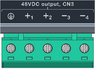
Connector at the Lexium™ MC connection module (CN3) |
Pin from CN3 |
Description |
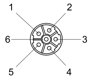
Pin from M23 connector |
Connector (M23, plug) at the Lexium™ MC12 multi carrier track |
|---|---|---|---|---|
|

|
Protective ground (earth) |
3 |
|
|
+1 |
48 Vdc DC bus voltage + |
2 |
||
|
+2 |
Not connected |
1 |
||
|
-3 |
48 Vdc DC bus voltage - |
4 |
||
|
-4 |
Not connected |
5 |
||
|
Not connected |
6 |
|||
|
Cable diagram Shield connected to housing on connector side. 
|
||||
| WARNING | |
|---|---|
An incorrect wiring may result in damage of components.
| CAUTION | |
|---|---|
Additional Wiring Examples
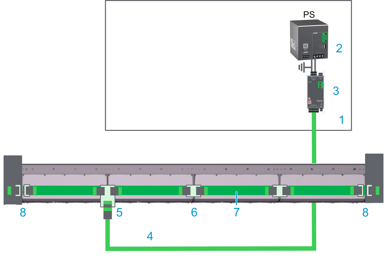
Open track
With an open track, you need a power disconnector (8) at each end of your track.
Also refer to Open Track.
|
Element |
Description |
|---|---|
|
1 |
Control cabinet |
|
2 |
Power supply |
|
3 |
Lexium™ MC connection module |
|
4 |
Lexium™ MC power cable with socket connector |
|
5 |
Lexium™ MC power interconnect with plug connector |
|
6 |
Lexium™ MC power interconnect without connector |
|
7 |
Internal DC bus connection |
|
8 |
Power disconnector |
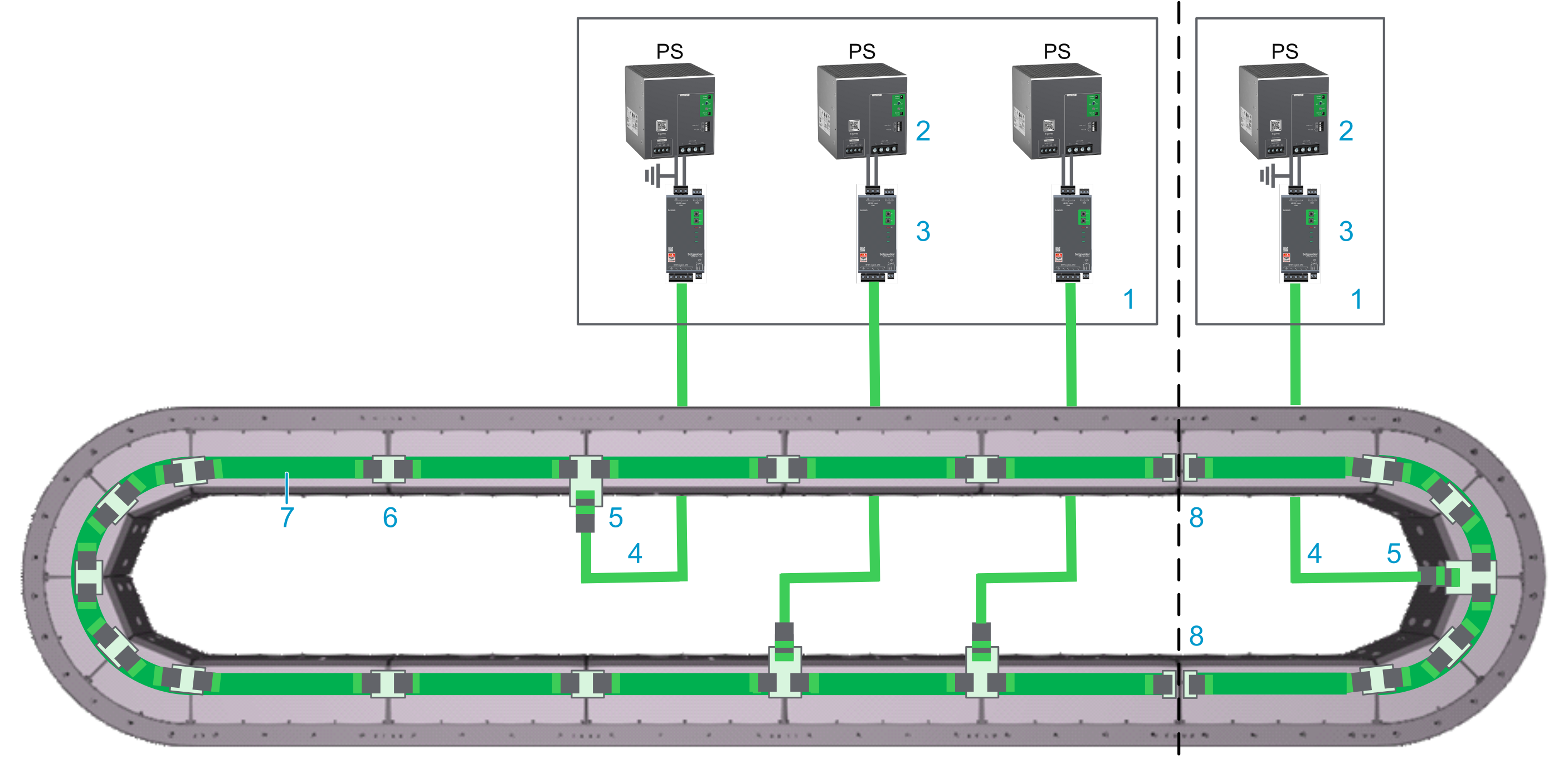
Track with two power supply groups
With a track with two power supply groups, you need power disconnectors (8) between the two power supply groups.
|
Element |
Description |
|---|---|
|
1 |
Control cabinet |
|
2 |
Power supply |
|
3 |
Lexium™ MC connection module |
|
4 |
Lexium™ MC power cable with socket connector |
|
5 |
Lexium™ MC power interconnect with plug connector |
|
6 |
Lexium™ MC power interconnect without connector |
|
7 |
Internal DC bus connection |
|
8 |
Power disconnector |
To ensure an equal load on the power supplies connected in parallel, the power cables in the same power group must have the same length.
| NOTICE | |
|---|---|