Description of the Rack iPC Universal and Optimized Motherboard
Rack iPC Universal and Optimized Board Introduction
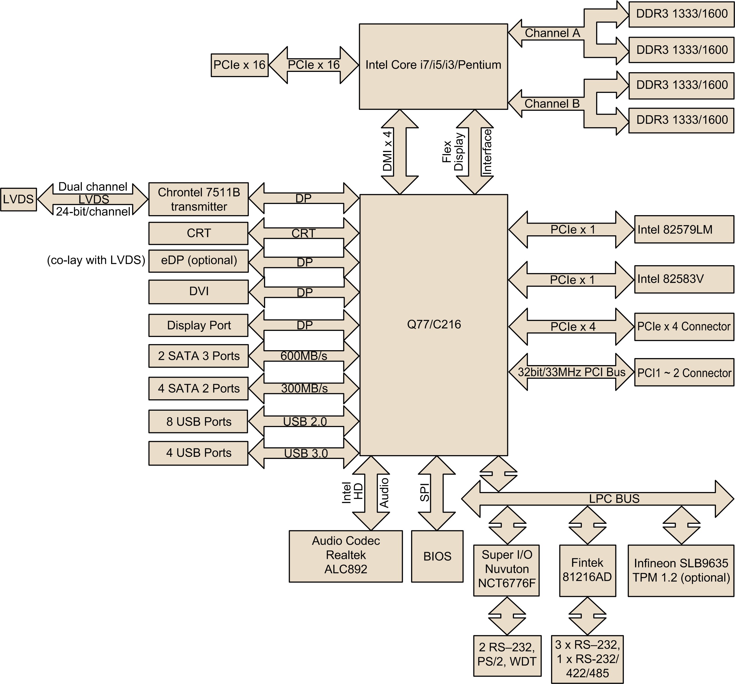
The Rack iPC Universal and Optimized motherboards are designed with the Intel® Q77/C216 chipsets used for industrial applications that require both performance computing and enhanced power management capabilities.
The Intel® Q77/C216 based board provides:
oRich I/O connectivity: Dual GbE LAN via PCIe x1 bus, 2 PCI 32- bit/33 MHz PCI slots, 1 PCIe x16 slot (Gen 3), 1 PCIe x4 slot (Gen 2), 8 USB 2.0 ports and 4 USB 3.0 ports.
oStandard micro ATX form factor with industrial features: The Rack iPC Universal and Optimized use a full featured micro ATX motherboard with balanced expandability and performance.
oWide selection of storage devices: SATA HDD, customers benefit from the flexibility of using the most suitable storage device for larger capacity
oOptimized integrated graphic solution: The Intel® flexible display interface supports versatile display options and a 32-bit 3D graphics engine.
The Universal system has:
oCPU processor: Intel® Core i3 2120 3.3 GHz
oBIOS: AMI EFI 64 Mbit/s SPI BIOS
oSystem chipset: Intel® Q77/C216
oSATA hard disk drive interface: Four on-board SATA connectors with data transmission rate up to 300 Mbit, and 2 on-board SATA connectors with data transmission rate up to 600 Mbit
The Optimized system has:
oCPU processor: Intel® Pentium G850 2.9 GHz/Celeron G540 2.5 GHz
oBIOS: AMI EFI 64 Mbit/s SPI BIOS
oSystem chipset: Intel® Q77/C216
oSATA hard disk drive interface: Four on-board SATA connectors with data transmission rate up to 300 Mbit, and 2 on-board SATA connectors with data transmission rate up to 600 Mbit
RAM: Up to 32 GB in 4 slots 240-pin DIMM sockets. Supports dual-channel DDR3 1333/1600 MHz SDRAM.
The Rack iPC supports either ECC buffered DIMMs or non-ECC unbuffered DIMMs. The Rack iPC does not support both ECC and non-ECC DIMMs in the same configuration.
oPCIe slot: 1 PCIe x16 expansion slot, 1 PCIe x4 expansion slot
oPCI bus: 2 PCI slots, 32-bit/33 MHz PCI 2.2 compliant
oEnhanced parallel port: Configured to LPT1 or disabled. Standard DB-25 female connector cable is an optional accessory. LPT1 supports EPP/SPP/ECP.
oSerial ports on rear panel: RS-232/422/485 with hardware auto-flow control, 4 RS-232, and 1 RS-232 sub-DB9 connectors.
oKeyboard and PS/2 mouse connector: 2 x 6-pin mini-DIN connectors located on the mounting bracket for easy connection to a PS/2 keyboard and mouse.
oUSB port: Supports up to 8 USB 2.0 ports with transmission rates up to 480 Mbps/s and 4 USB 3.0 ports with transmission rates up to 5 Gbps.
oGPIO: Rack iPC Universal and Optimized support 8-bit GPIO from super I/O for general-purpose control applications.
oController: Intel® HD graphics
oDisplay memory: 1 GB maximum shared memory when 2 GB or more of system memory is installed
oDVI: Supports DVI up to 1920 x 1200 resolution at 60 Hz refresh rate
oVGA: Supports VGA up to 2048 x 1536 resolution at 75 Hz refresh rate
oLVDS: Supports LVDS up to resolution 1920 x 1200
oDisplay port: Supports a maximum resolution of 2560 x 1600 at 60 Hz
oeDP: Supports a maximum resolution of 1920 x 1200 at 60 Hz
oTriple display: VGA+eDP (or LVDS)+DP, VGA+eDP(or LVDS)+DVI, VGA+DP+DVI
oDual display: VGA+eDP (or LVDS), VGA+DVI, eDP(or LVDS)+DVI, VGA+DP, DP+ DVI, LVDS+DP
oSupports dual 10/100/1000 Mbps/s Ethernet ports via PCI express x 1 bus which provides 500 MB/s data transmission rate.
oController: LAN1: Intel® 82579LM; LAN2: Intel® 82583 V
oWatchdog timer: Used to generate a system reset. The watchdog timer is programmable, with each unit equal to 1 second or 1 minute (255 levels)
Board Features and Board Layout
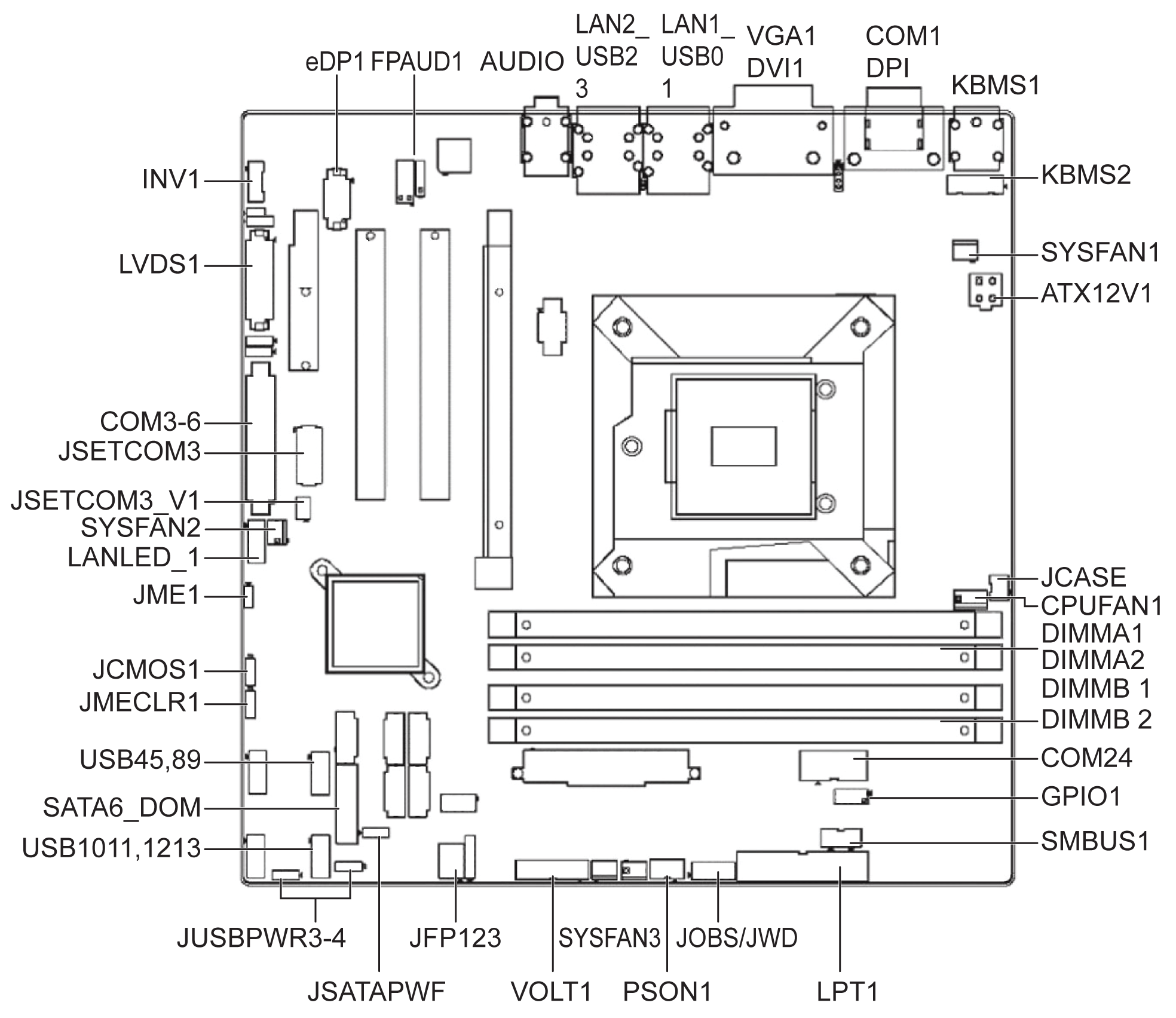
The figure shows Universal and Optimized board layout, jumper, and connector locations:

The table lists the Rack iPC Universal and Optimized jumpers and their function:
|
Label |
Function |
|---|---|
|
JFP1 |
Power switch/HDD LED/SMBus/speaker |
|
JFP2 |
Power LED and keyboard lock |
|
CMOS1 |
CMOS clear (default 1-2) |
|
PSON1 |
AT(1-2) / ATX(2-3) (default 2-3) |
|
JWDT1+JOBS1 |
Watchdog reset and OBS alarm |
|
JCASE1 |
Case open pin header |
|
JLVDS1 |
Voltage 3.3 V/5 V/12 V selector for LVDS1 connector (default 1-2, 3.3 V) |
|
JLVDS_CLT1 |
Brightness control selector for analog or digital (default 1-2, analog) |
|
JEME1 |
Intel AMT disable jumper |
|
JMECLR1 |
Clear AMT setting |
|
JUSBPWR1 |
USB port 0-1 power source switch between +5 Vsb and +5 V |
|
JUSBPWR2 |
USB port 2-3 power source switch between +5 Vsb and +5 V |
|
JUSBPWR3 |
USB port 4/5/8/9 power source switch between +5 Vsb and +5 V |
|
JUSBPWR4 |
USB port 10/11/12/13 power source switch between +5 Vsb and +5 V |
The table lists the Rack iPC Universal and Optimized connectors and their function:
|
Label |
Function |
|---|---|
|
LPT1 |
Parallel port, supports SPP/EPP/ECP mode |
|
LVDS1 |
LVDS1 connector |
|
INV1 |
LVDS1 inverter connector |
|
COM3456 |
Serial port connectors (RS-232) |
|
USB45 |
USB port 4, 5 (on board) |
|
USB89 |
USB port 8, 9 (on board) |
|
USB1011 |
USB port 10, 11 (on board) |
|
USB1213 |
USB port 12, 13 (on board) |
|
VGA |
VGA connector |
|
COM1 |
Serial port connector (RS-232) |
|
KBMS1 |
PS/2 keyboard and mouse connector |
|
CPUFAN1 |
CPU FAN connector(4-pin) |
|
SYSFAN1 |
System FAN1 connector(3-pin) |
|
SYSFAN2 |
System FAN2 connector(3-pin) |
|
SYSFAN3 |
System FAN3 connector(3-pin) |
|
SYSFAN4 |
System FAN4 connector(3-pin) |
|
LAN1_USB01 |
LAN1 / USB port 0, 1 |
|
LAN2_USB23 |
LAN2 / USB port 2, 3 |
|
AUDIO1 |
Audio connector |
|
SPDIF_OUT1 |
SPDIF audio out pin header |
|
FPAUD1 |
HD audio front panel pin header |
|
PCIEX16_1 |
PCIe x16 slot |
|
SATA1 |
Serial ATA data connector 1 |
|
SATA2 |
Serial ATA data connector 2 |
|
SATA3 |
Serial ATA data connector 3 |
|
SATA4 |
Serial ATA data connector 4 |
|
SATA5 |
Serial ATA data connector 5 |
|
SATA6 |
Serial ATA data connector 6 |
|
DIMMA1 |
Channel a DIMM1 |
|
SPI_CN1 |
SPI flash update connector. |
|
GPIO1 |
GPIO header |
|
ATX12V1 |
ATX 12 V auxiliary power connector (for CPU) |
|
ATXPWR1 |
ATX 20-pin main power connector (for system) |
|
DVI |
DVI-D connector on rear panel |
|
COM2 |
Serial port COM2, pin header 2x5 |
|
EDP1 |
eDP connector (2x10 pin header) |
|
JTAG |
Joint test action group connector 2x5 P |
|
SMBUS1 |
SMBUS expansion pin header 1x4 P |
The figure shows the block diagram of the Universal and Optimized motherboards:
