The HMISCUxB5 HMI controllers have embedded analog I/O:
o2 analog inputs
o2 analog outputs
For information about the technical characteristics of the analog I/O, refer to the Hardware Guide.
Accessing the Analog I/O Configuration Window
|
Step |
Description |
|---|---|
|
1 |
Click HMISCUxx5 > Embedded Functions > Analog. |
|
2 |
Select the I/O Configuration tab. |
Analog I/O Configuration Window
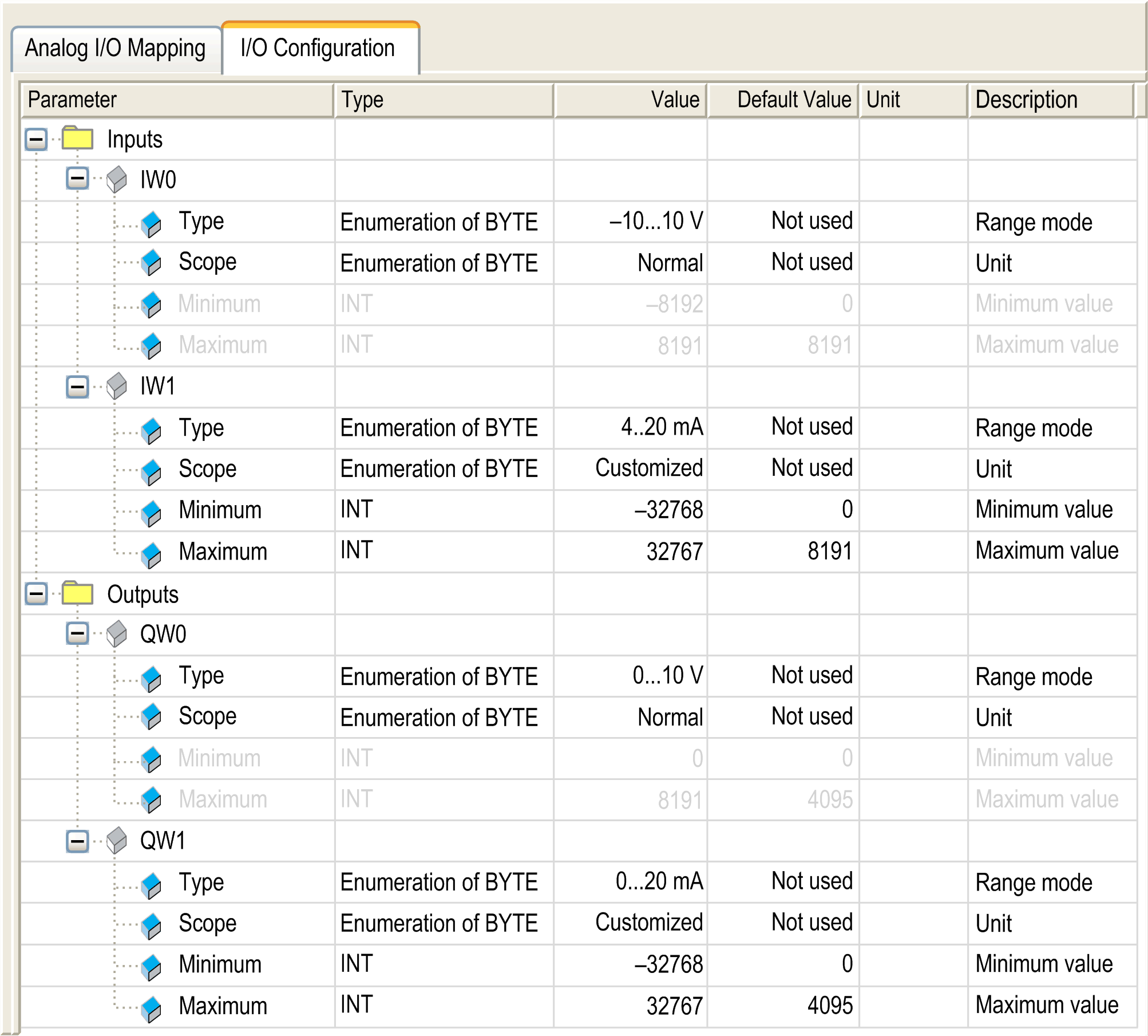
This window allows you to configure the analog I/O:

NOTE: The parameter is unavailable if the selection displays as gray in color.
NOTE: Embedded analog I/Os are always physically updated by the MAST task.
To configure the HMI SCU, select the I/O Configuration tab.
The table describes the analog parameters configuration:
|
Parameter |
Value |
Description |
Constraint |
|
|---|---|---|---|---|
|
Type |
Not used * – 10...10 V 0...10 V 0...20 mA 4...20 mA |
Range mode |
– |
|
|
Scope |
Normal * Customized |
Unit |
Available if Type value is defined. |
|
|
Minimum |
Normal Analog input |
– 10...10 V: – 8192 0...10 V: 0 0...20 mA: 0 4...20 mA: 0 |
Minimum value |
Not configurable. |
|
Normal Analog output |
– 10...10 V: – 2048 0...10 V: 0 0...20 mA: 0 4...20 mA: 0 |
Not configurable. |
||
|
Customized Analog I/O |
– 10...10 V: – 32768 0...10 V: – 32768 0...20 mA: – 32768 4...20 mA: – 32768 |
Inferior that the configured maximum. Configured minimum must be less than the configured maximum. |
||
|
Maximum |
Normal Analog input |
– 10...10 V: 8191 0...10 V: 16383 0...20 mA: 16383 4...20 mA: 16383 |
Maximum value |
Not configurable. |
|
Normal Analog output |
– 10...10 V: 2047 0...10 V: 4095 0...20 mA: 4095 4...20 mA: 4095 |
Not configurable. |
||
|
Customized Analog I/O |
– 10...10 V: 32767 0...10 V: 32767 0...20 mA: 32767 4...20 mA: 32767 |
Superior that the configured minimum. Configured maximum must be more than the configured minimum. |
||
|
* parameter default value |
||||
If you have physically wired the analog channel for a voltage signal and you configure the channel for a current signal in SoMachine, you may damage the analog circuit.
|
NOTICE |
|
INOPERABLE EQUIPMENT |
|
Verify that the physical wiring of the analog circuit is compatible with the software configuration for the analog channel. |
|
Failure to follow these instructions can result in equipment damage. |
Analog to Digital Conversion Rate
Analog-to-digital conversion rate for data acquisition is made using the converter hardware. All analog I/O that are configured are converted every 2 ms.
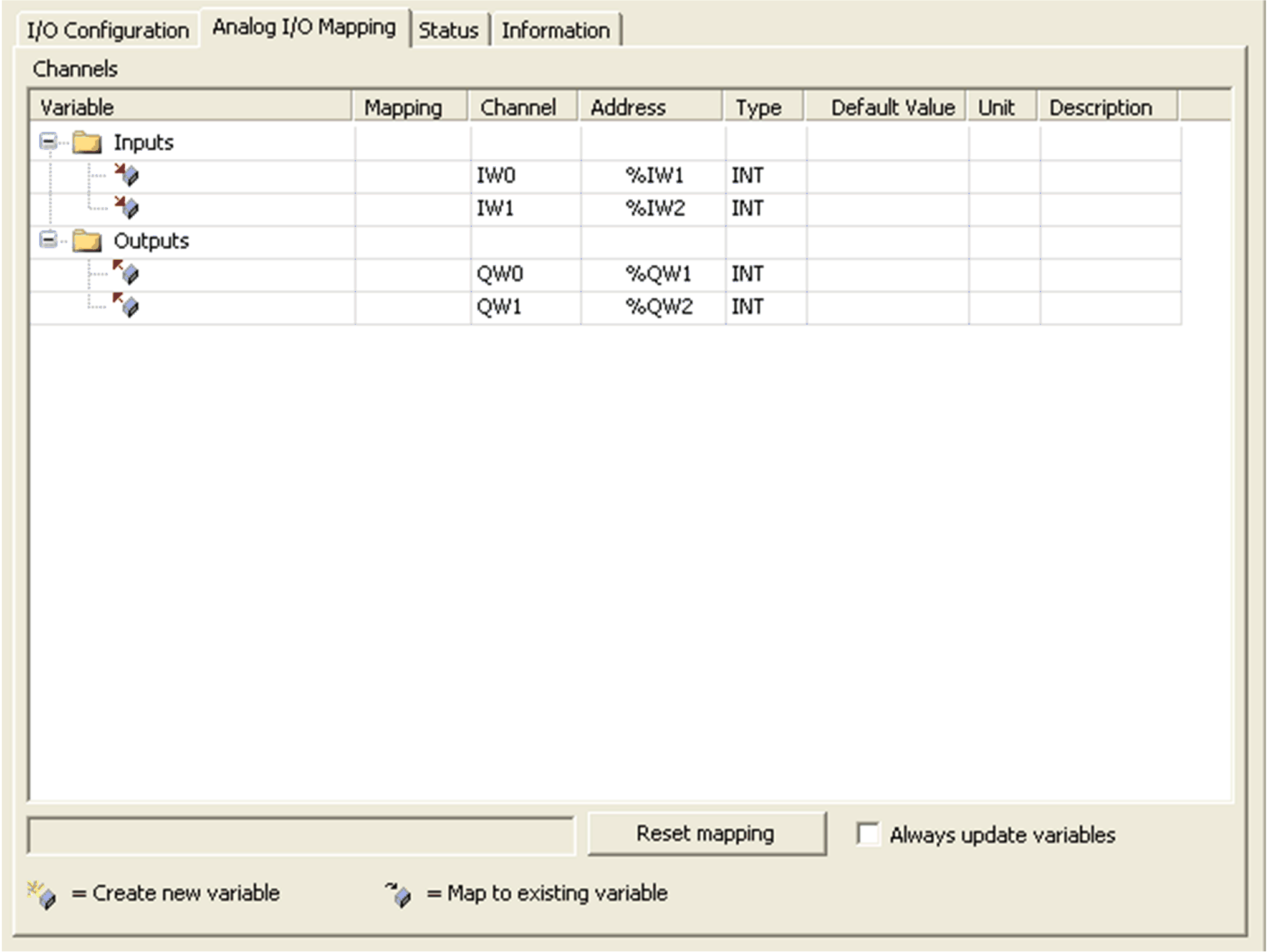
Variables can be defined and named in the Analog I/O Mapping tab. Additional information such as topological addressing is also provided in this tab.
This window shows the Analog I/O Mapping tab:

The table describes the I/O mapping configuration:
|
Variable |
Channel |
Type |
Default value |
Description |
|---|---|---|---|---|
|
Inputs |
IW0 |
INT |
– |
Current value of the input 0 |
|
IW1 |
Current value of the input 1 |
|||
|
Outputs |
QW0 |
INT |
– |
Current value of the output 0 |
|
QW1 |
Current value of the output 1 |