Analog Temperature Embedded Function
The HMISCUxB5 HMI controllers have embedded analog temperature with 2 inputs. The HMI SCU is designed for various sensor types. The sensor type must be specified because of the different adjustment values.
For information about the technical characteristics of the analog temperature inputs, refer to the Hardware Guide.
Access to Analog Temperature Configuration
|
Step |
Action |
|---|---|
|
1 |
Click HMISCUxx5 > Embedded Functions > Temperature. |
|
2 |
Select the I/O Configuration or Temperature I/O Mapping tab. |
Analog Temperature Input Configuration Window
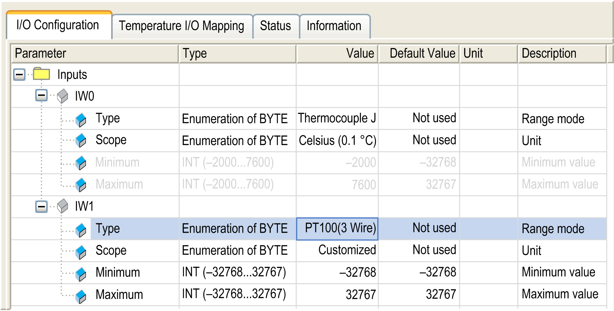
This window allows you to configure the analog temperature inputs:

NOTE: Embedded analog I/Os are always physically updated by the MAST task.
The table describes the analog input parameter configuration:
|
Parameter |
Value |
Description |
Constraint |
|
|---|---|---|---|---|
|
Type |
Not used * Thermocouple J Thermocouple K Thermocouple R Thermocouple B Thermocouple S Thermocouple T Thermocouple E Thermocouple N PT100 (2/4 wire) PT1000 (2/4 wire) NI100 (2/4 wire) NI1000 (2/4 wire) PT100 (3 wire) PT1000 (3 wire) NI100 (3 wire) NI1000 (3 wire) |
Range mode |
– |
|
|
Scope |
Not used * Normal Customized Celsius (0.1 °C) Fahrenheit (0.1 °F) |
Unit |
Available if Type value is defined. |
|
|
Minimum |
Normal |
0 |
Minimum value |
Not configurable. |
|
Customized |
– 32768 |
Minimum value |
Lowest configurable value. |
|
|
Celsius |
Thermocouple J: –2000 Thermocouple K: –2400 Thermocouple R: 0 Thermocouple B: 2000 Thermocouple S: 0 Thermocouple T: –2000 Thermocouple E: –2000 Thermocouple N: –2000 PT100: –2000 PT1000: –2000 NI100: –500 NI1000: –500 |
Minimum value |
Not configurable. |
|
|
Fahrenheit |
Thermocouple J: –3280 Thermocouple K: –4000 Thermocouple R: 32 Thermocouple B: –3920 Thermocouple S: 32 Thermocouple T: –3280 Thermocouple E: –3280 Thermocouple N: –3280 PT100: –3280 PT1000: –3280 NI100: -580 NI1000: -580 |
Minimum value |
Not configurable. |
|
|
Maximum |
Normal |
65535 |
Maximum value |
Not configurable. |
|
Customized |
32767 |
Maximum value |
Highest configurable value. |
|
|
Celsius |
Thermocouple J: 7600 Thermocouple K: 13700 Thermocouple R: 16000 Thermocouple B: 18000 Thermocouple S: 16000 Thermocouple T: 4000 Thermocouple E: 9000 Thermocouple N: 13000 PT100: 6000 PT1000: 6000 NI100: 2000 NI1000: 2000 |
Maximum value |
Not configurable. |
|
|
Fahrenheit |
Thermocouple J: 14000 Thermocouple K: 24980 Thermocouple R: 29120 Thermocouple B: 32720 Thermocouple S: 29120 Thermocouple T: 7520 Thermocouple E: 16520 Thermocouple N: 23720 PT100: 11120 PT1000: 11120 NI100: 3920 NI1000: 3920 |
Maximum value |
Not configurable. |
|
|
* parameter default value |
||||
If you have physically wired the analog channel for a voltage signal and you configure the channel for a current signal in SoMachine, you may damage the analog circuit.
|
NOTICE |
|
INOPERABLE EQUIPMENT |
|
Verify that the physical wiring of the analog circuit is compatible with the software configuration for the analog channel. |
|
Failure to follow these instructions can result in equipment damage. |
NOTE:
oTo reduce cycle time, do not activate a channel when there is no sensor connected.
oThe data type is always INT which is a 16 bit integer value. The minimum and maximum values are shown according to the entries in the table above. (for example, for thermocouple J in Celsius the Type would read: INT(– 2000...7600))
oThe parameter is unavailable if the selection displays as gray in color.
Analog to Digital Conversion Rate
Analog-to-digital conversion rate for data acquisition is made using the converter hardware. All temperature analog I/Os that are configured are converted every 2 ms.
Terminal Temperature (Cold Junction) Compensation
Terminal Temperature (Cold Junction) Compensation is measured and calculated internally. No extra temperature measurement of the terminal is required.
Temperature I/O Mapping Window
Variables can be defined and named in the Temperature I/O Mapping window. Additional information such as topological addressing is also provided in this tab.
The table describes the I/O mapping configuration:
|
Variable |
Channel |
Type |
Default Value |
Description |
|---|---|---|---|---|
|
Inputs |
IW0 |
INT |
– |
Current value of the input 0 |
|
IW1 |
Current value of the input 1 |