Additional signal sequence diagrams
Temporary intermediate states are not illustrated in the signal sequence diagrams. Only typical input signal combinations are illustrated in these diagrams. Other signal combinations are possible.
The most significant areas within the signal sequence diagrams are highlighted in color.
Refer also to the diagram found in the overview for this function block.
The signal sequence diagrams in this documentation possibly omit particular diagnostic codes. For example, a diagnostic code is possibly not shown if the related function block state is a temporary transition state and only active for one cycle of the Safety Logic Controller.
Only typical input signal combinations are illustrated. Other signal combinations are possible.
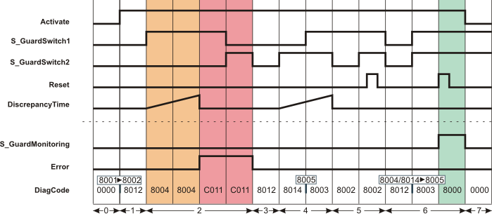
Errors after discrepancy time exceeded
This diagram is based on typical monitoring of a guard with two-stage interlocking, where both position switches connected to inputs S_GuardSwitch1 and S_GuardSwitch2 do not switch within the time set at DiscrepancyTime:
S_StartReset = SAFEFALSE: Start-up inhibit after the function block has been activated and the Safety Logic Controller has started up
S_AutoReset = SAFEFALSE: Restart inhibit after the safety equipment has been closed (in other words, after the SAFETRUE signals have returned at inputs S_GuardSwitch1 and S_GuardSwitch2).
|
0 |
The function block is not yet activated (Activate = FALSE). As a result, all outputs are FALSE or SAFEFALSE. |
|
1 |
The function block is activated (input Activate = TRUE). The safety equipment is open (S_GuardSwitch1 and S_GuardSwitch2 = SAFEFALSE). |
|
2 |
The safety equipment is closed, whereby S_GuardSwitch1 switches to SAFETRUE first. This initiates measurement of the discrepancy time. Since S_GuardSwitch2 does not switch to SAFETRUE within the time set at DiscrepancyTime either, an error message is output after the discrepancy time has elapsed: Output Error = TRUE. The S_GuardMonitoring output remains SAFEFALSE. |
|
3 |
The door is opened again. This switches both inputs S_GuardSwitch1 and S_GuardSwitch2 to SAFEFALSE. This state causes the error message to be removed: The Error output becomes FALSE. |
|
4 |
The safety equipment is closed again, which causes S_GuardSwitch2 to switch to SAFETRUE first. This initiates measurement of the discrepancy time. S_GuardSwitch1 also switches to SAFETRUE within the discrepancy time. The S_GuardMonitoring output remains SAFEFALSE, however, as the restart inhibit has not yet been removed by a positive signal edge at the Reset input. |
|
5 |
The S_GuardSwitch2 input becomes SAFEFALSE. The function block interprets this as the safety equipment opening and expects S_GuardSwitch1 to be switched to SAFEFALSE as well. The switch back to SAFETRUE at S_GuardSwitch2 does not initiate measurement of the discrepancy time, as S_GuardSwitch1 was not SAFEFALSE at this time. S_GuardSwitch1 and S_GuardSwitch2 are SAFETRUE, but a positive edge at Reset has no effect, because the function block only recognizes the closing of the safety equipment as valid once both S_GuardSwitch1 and S_GuardSwitch2 are SAFEFALSE (in other words, after the safety equipment has been fully opened). |
|
6 |
The safety equipment is opened (S_GuardSwitch1 and S_GuardSwitch2 are SAFEFALSE). The safety equipment is then closed. Both inputs S_GuardSwitch1 and S_GuardSwitch2 become SAFETRUE at the same time. A positive edge at the Reset input removes the restart inhibit (set with S_AutoReset = SAFEFALSE) and the S_GuardMonitoring output becomes SAFETRUE. |
|
7 |
The S_GuardMonitoring output becomes SAFEFALSE, as activation of the function block is reset at the Activate input (Activate = FALSE). |