SF_ModeSelector
The following description is valid for the function block SF_ModeSelector_V1_0z, Version 1.0z (where z = 0 to 9).
Short description
|
The safety-related SF_ModeSelector function block evaluates the states of a mode selector switch with up to eight positions. A mechanical mode selector switch can be used to set a specific operating mode (e.g., service mode, setup mode, cleaning mode, etc.). Each operating mode can have a different safety-related function. |
|
Function block inputs
Click the corresponding hyperlinks to obtain detailed information on the items below.
|
Name |
Short description |
Value |
|---|---|---|
|
State-controlled input for activating the function block. Data type: BOOL Initial value: FALSE |
|
|
|
State-controlled inputs for the status of the connected mode selector switch. There must only ever be one SAFETRUE signal at one of the inputs. Data type: SAFEBOOL Initial value: SAFEFALSE If more than one operating mode is detected at the mode selector switch, this behavior immediately leads to an error. If no operating mode is selected (S_Mode0 to S_Mode7 = SAFEFALSE), this leads to an error after the time set at ModeMonitorTime has elapsed.
NOTE:
If the set operating mode is locked by S_Unlock = SAFEFALSE, the signal combination at the inputs (S_Mode0 to S_Mode7) is not evaluated. |
|
|
|
State-controlled input for locking/unlocking mode selector switching (S_Mode0 to S_Mode7) with, for example, a key switch. Data type: SAFEBOOL Initial value: SAFEFALSE |
|
|
|
Edge-triggered input for confirming or enabling the operating mode set at S_Mode0 to S_Mode7. Data type: SAFEBOOL Initial value: SAFEFALSE Manual confirmation is required (via a SAFEFALSE > SAFETRUE edge at the S_SetMode input) if AutoSetMode is set to FALSE. |
|
|
|
State-controlled input for specifying the automatic acceptance of the operating mode set at inputs S_Mode0 to S_Mode7. Data type: BOOL Initial value: FALSE
NOTE:
If the set operating mode is locked by S_Unlock = SAFEFALSE, no switchover to another operating mode is performed. Automatic acceptance of the set operating mode (AutoSetMode = TRUE) must only be used if it is certain that starting up the machine/system will not lead to a hazardous situation or that a start-up will be prevented in a suitable manner at another location or using other means. Refer to the first hazard message below this table. |
|
|
|
Input for specifying the maximum permissible switchover time for switching the operating mode. Data type: TIME Initial value: #0ms All inputs may show a SAFEFALSE signal simultaneously during the time set at ModeMonitorTime. After this, a simultaneous SAFEFALSE signal at S_Mode0 to S_Mode7 leads to an error (Error = TRUE). If more than one operating mode is detected at the mode selector switch, this behavior immediately leads to an error. |
Enter a time value according to your risk analysis. Refer to the second hazard message below this table. |
|
|
Edge-triggered input for the reset signal: Resetting error messages when the cause of the error is no longer present. Resetting an error by means of a positive signal edge at the Reset input can cause the S_Mode0Sel to S_Mode7Sel output to switch to SAFETRUE immediately (depending on the status of the other inputs). Refer to the third hazard message below this table. Data type: BOOL Initial value: FALSE
NOTE:
Resetting does not occur with a negative (falling) edge, as specified by standard EN ISO 13849-1, but with a positive (rising) edge. |
|
| WARNING | |
|---|---|
| WARNING | |
|---|---|
| WARNING | |
|---|---|
Function block outputs
|
Name |
Short description |
Value |
|---|---|---|
|
Output for signaling "Function block activated/not activated". Data type: BOOL |
|
|
|
Outputs for signaling the set operating mode. There can only ever be one output showing a SAFETRUE signal at any one time. Data type: SAFEBOOL |
|
|
|
Output for signaling whether a signal combination is output at the S_Mode0Sel to S_Mode7Sel outputs. |
|
|
|
Output for error message. Data type: BOOL |
|
|
|
Output for diagnostic message. Data type: WORD |
Diagnostic message of the function block. The possible values are listed and described in the topic "Diagnostic codes". |
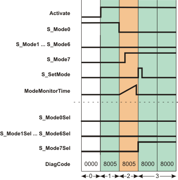
Signal sequence diagram
The diagram shows the signal sequence for a valid operating mode switchover within the monitoring time set at ModeMonitorTime.
-
AutoSetMode = FALSE: Acceptance of the set operating mode requires manual confirmation via a positive edge at the S_SetMode input.
-
S_Unlock = SAFETRUE: Operating mode switchover is possible.
The other signal sequence diagram can be taken into account.
The signal sequence diagrams in this documentation possibly omit particular diagnostic codes. For example, a diagnostic code is possibly not shown if the related function block state is a temporary transition state and only active for one cycle of the Safety Logic Controller.
Only typical input signal combinations are illustrated. Other signal combinations are possible.
|
0 |
The function block is not yet activated (Activate = FALSE). As a result, all outputs are FALSE or SAFEFALSE. |
|
1 |
The function block is activated (Activate = TRUE); the inputs are now evaluated. The specification for operating mode 0 is present at the inputs (input S_Mode0 is SAFETRUE). However, as no manual confirmation for the operating mode switchover is detected at the S_SetMode input (this is necessary since AutoSetMode = FALSE), the S_Mode0Sel output remains SAFEFALSE in spite of the specification (S_Mode0 = SAFETRUE). |
|
2 |
The mode selector switch is actuated, there is a request to switch to operating mode 7. Input S_Mode0 becomes SAFEFALSE; this switch initiates measurement of the monitoring time. S_Mode7 switches to SAFETRUE before the time set at ModeMonitorTime has elapsed. Although operating mode 7 has now been set as the new mode, it is not yet active, as a manual acceptance was specified with AutoSetMode = FALSE. A positive edge is required at S_SetMode to activate the operating mode at the S_Mode7Sel output. |
|
3 |
The positive signal edge at the S_SetMode input enables the set operating mode 7, and the S_Mode7Sel output becomes SAFETRUE. |
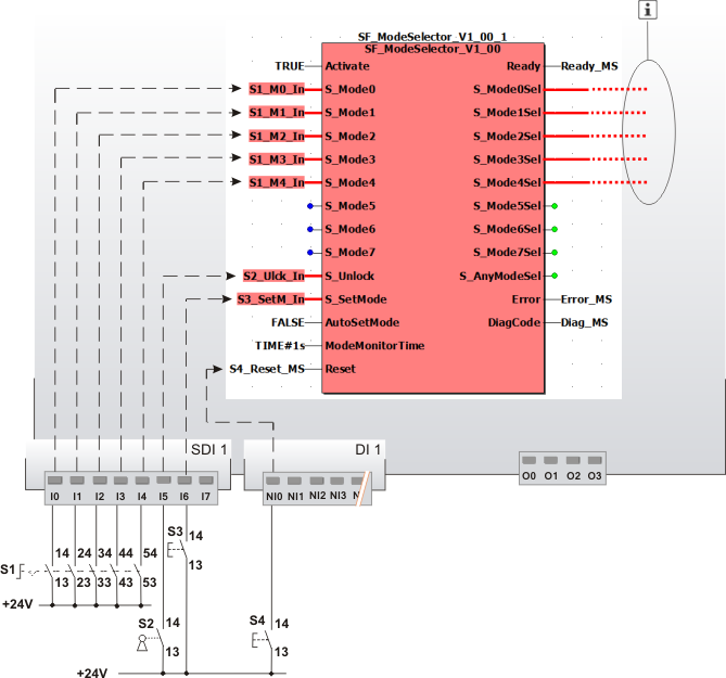
Application example
This example uses a five-stage mode selector switch S1 to show how operating modes are selected.
The signals of the five N/O contacts of the mode selector switch are connected to the five input terminals I0 to I4 of safety-related input device SDI 1. The signals are assigned to the global I/O variables and the function block inputs are connected as follows:
|
Terminal |
Global I/O variable |
Function block input |
|---|---|---|
|
I0 |
S1_M0_In |
S_Mode0 |
|
I1 |
S1_M1_In |
S_Mode1 |
|
I2 |
S1_M2_In |
S_Mode2 |
|
I3 |
S1_M3_In |
S_Mode3 |
|
I4 |
S1_M4_In |
S_Mode4 |
As a five-stage mode selector switch is evaluated, the function block inputs S_Mode5 to S_Mode7 remain unconnected.
A key switch S2 is connected to input terminal I5 of the safety-related input device SDI 1. The input signal is assigned to the global I/O variable S2_Ulck_In, which in turn is connected to the S_Unlock input of the function block. Closing the key switch (S_Unlock = SAFEFALSE) locks the operating mode that has been set.
A FALSE constant is connected to the AutoSetMode input, which means that a manual confirmation of the set operating mode is required at the S_SetMode input. Button S3 is connected to input terminal I6 of the safety-related input device SDI 1 for this purpose. Its input signal is assigned to the global I/O variable S3_SetM_In, which in turn is connected to the S_SetMode input of the function block.
A reset button S4, which is connected to input terminal NI0 of the standard input device DI 1 is used for resetting error messages (positive signal edge at the Reset input of the function block). Its signal is assigned to the global I/O variable S4_Reset_MS, which in turn is connected to the Reset input of the function block.
The S_Mode0Sel to S_Mode4Sel enable outputs of the SF_ModeSelector function block are connected to the inputs of other safety-related functions/function blocks. As a five-stage mode selector switch is evaluated, the function block outputs S_Mode5Sel to S_Mode7Sel are not relevant and can remain unconnected.
|
S1 |
Mode selector switch with 5 switch positions |
|
S2 |
Key switch (blocking the mode selection) |
|
S3 |
Confirmation |
|
S4 |
Reset |
|
|
See note above the illustration. |

The second application example and the accompanying notes can be taken into account.
Detailed information
Additional information is available in the following sections: