Take extra care with respect to vibration levels when installing or moving the S-Panel PC and the Enclosed PC. If you move the S-Panel PC and the Enclosed PC while it is installed in a rack equipped with caster wheels, it may undergo excessive shock and vibration.
|
|
|
EXCESSIVE VIBRATION |
|
oPlan your installation activities so that shock and vibration tolerances in the unit are not exceeded. oEnsure that the installation panel opening and thickness are within the specified tolerances. oBefore mounting the Magelis Industrial PC into a cabinet or panel, ensure that the installation gasket is in place. The installation gasket provides additional protection from vibration. oTighten the installation fasteners using a torque of 0.5 Nm (4.5 lb-in). |
|
Failure to follow these instructions can result in injury or equipment damage. |
The gasket is required to meet the protection ratings (IP••/Type 4X indoor) of the S-Panel PC. It provides additional protection from vibration.
NOTE: IP••/Type 4X indoor or Type 4 is not part of UL certification.
|
|
|
LOSS OF SEAL |
|
oInspect the gasket before installation or reinstallation, and periodically as required by your operating environment. oReplace the complete Magelis Industrial PC if visible scratches, tears, dirt, or excessive wear are noted during inspection. oDo not stretch the gasket unnecessarily or allow the gasket to contact the corners or edges of the frame. oEnsure that the gasket is fully seated in the installation groove. oInstall the Magelis Industrial PC into a panel that is flat and free of scratches or dents. oTighten the installation fasteners using a torque of 0.5 Nm (4.5 lb-in). |
|
Failure to follow these instructions can result in injury or equipment damage. |
Installation of the S-Panel PC
The installation gasket and installation fasteners are required for the easy installation of the S-Panel PC. The panel mounting process of the easy installation can be completed by one person.
NOTE: For easy installation of the S-Panel PC, the suggested mounting panel thickness can be up to 2 mm (0.079 in).
|
Step |
Action |
|---|---|
|
1 |
Check that the gasket is correctly attached to the S-Panel PC. NOTE: When checking the gasket, avoid contact with the sharp edges of the S-Panel PC frame, and insert the gasket completely into its groove. |
|
2 |
Release the 2 screws at the bottom of the S-Panel PC: 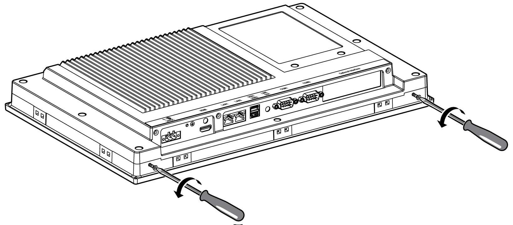
|
|
3 |
Loosen the 2 cross-slotted screws from the top of the S-Panel PC to raise the snap hook: 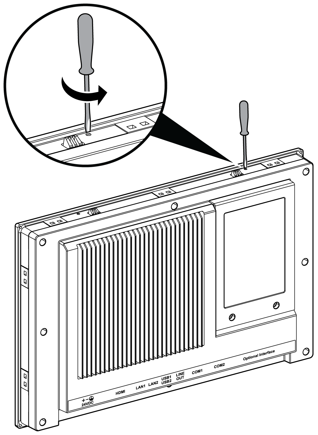
|
|
4 |
Install the S-Panel PC in the panel opening and push it into the wall. The snap hook holds the S-Panel PC to the wall: 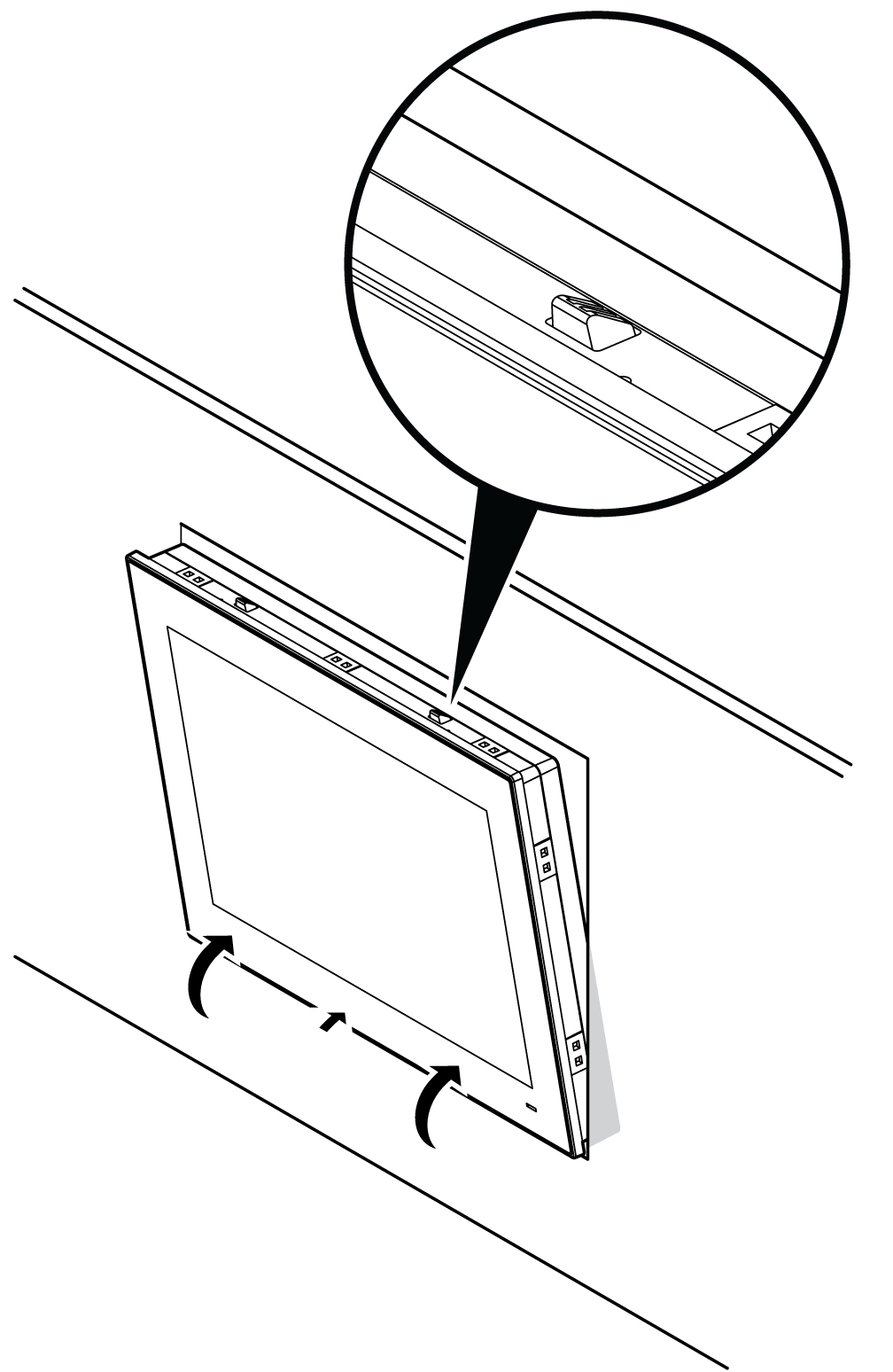
|
|
5 |
Insert the 10 installation fasteners securely into the slots of the S-Panel PC: 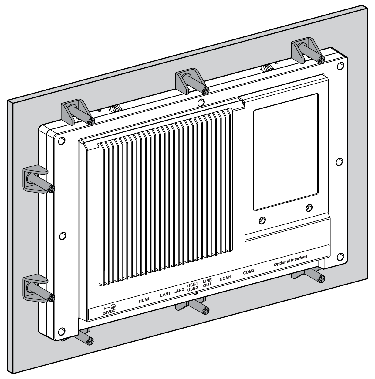
|
|
6 |
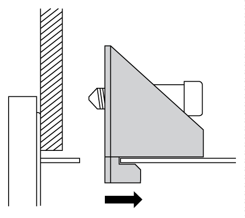
Insert each fastener in its corresponding slot and pull the fastener back until it is flush with the rear of the fastener hole: 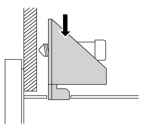
|
|
7 |
Tighten each of the cross-slotted fastener screws, and secure the S-Panel PC in place: 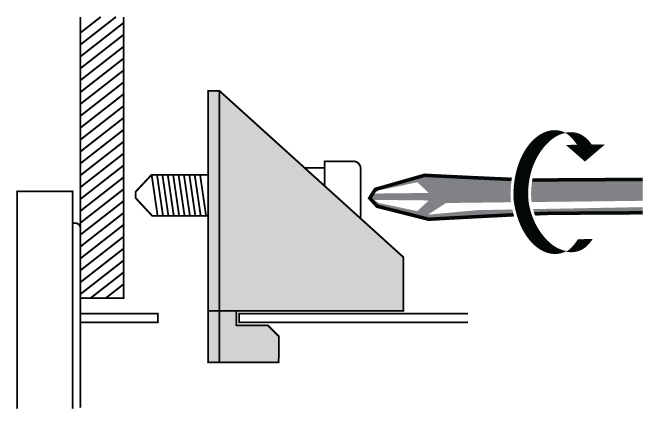
NOTE: To ensure a high degree of moisture resistance, use a torque of 0.5 Nm (4.5 lb-in). |
|
8 |
The angle of the unit is tilted no more than the amount allowed by the mounting orientation requirements. |
|
|
|
OVERTORQUE AND LOOSE HARDWARE |
|
oDo not exert more than 0.5 Nm (4.5 lb-in) of torque when tightening the installation fastener, enclosure, accessory, or terminal block screws. Tightening the screws with excessive force can damage the installation fastener. oWhen fastening or removing screws, ensure that they do not fall inside the Magelis Industrial PC chassis. |
|
Failure to follow these instructions can result in injury or equipment damage. |
NOTE: The installation fasteners are required for IP••/Type 4X indoor protection. IP••/Type 4X indoor or Type 4 is not part of UL certification.
Installation of the Enclosed PC with the VESA Mounting
|
Step |
Action |
|---|---|
|
1 |
Fasten the VESA mounting on the rear side of the Enclosed PC: 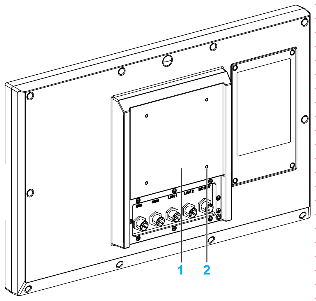
1 VESA plate position (size 100 x 100 mm) 2 4 x VESA mount screws for attachment |
|
2 |
The angle of the unit is tilted no more than the amount allowed by the mounting orientation requirements: 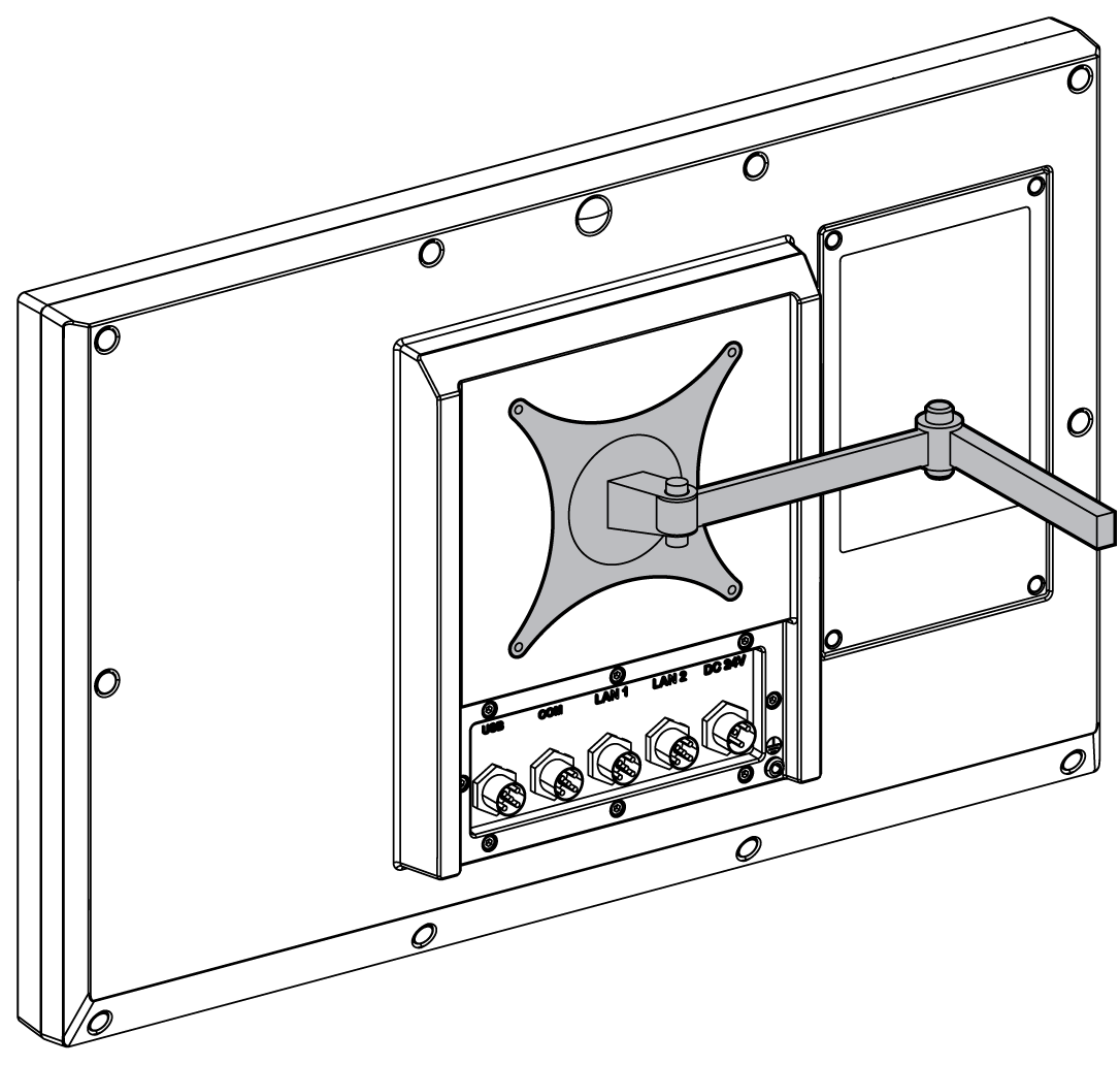
|