Optional Interface Installation
Before installing or removing an interface module, shut down Windows in an orderly fashion and remove the power from the device.
|
|
|
HAZARD OF ELECTRIC SHOCK, EXPLOSION OR ARC FLASH |
|
oRemove all power from the device before removing any covers or elements of the system, and prior to installing or removing any accessories, hardware, or cables. oUnplug the power cable from both the Magelis Industrial PC and the power supply. oAlways use a properly rated voltage sensing device to confirm power is off. oReplace and secure all covers or elements of the system before applying power to the unit. oUse only the specified voltage when operating the Magelis Industrial PC. The DC unit is designed to use 24 Vdc input. |
|
Failure to follow these instructions will result in death or serious injury. |
Compatible table:
|
Part number |
Description |
S-Panel PC |
|---|---|---|
|
HMIYMINUSB1 |
Interface USB 3.0, 2 x USB |
Yes |
|
HMIYMINAUD1 |
Interface audio BKT, 1 x LI/LO/MIC |
Not applicable |
|
HMIYMINSL24851 |
Interface 2 x RS-422/485 isolation |
Yes |
|
HMIYMINSL44851 |
Interface 4 x RS-422/485 isolation, DB 37, cable |
Yes |
|
HMIYMINSL22321 |
Interface 2 x RS-232 isolatation |
Yes |
|
HMIYMINSL42321 |
Interface 4 x RS-232, DB37, cable |
Yes |
|
HMIYMINAUD21 |
Interface audio 1 x LI/LO/MIC |
Yes |
|
HMIYMINATPM201 |
Interface TPM 2.0 |
Not applicable |
|
HMIYMINIO1 |
Interface 16DI/8DO, 1 x DB37, 2 m cable |
Yes |
|
HMIYMINWIFI1 |
Interface WiFi, AC3160, 2 x antenna |
Yes |
|
HMIYMINGPRS1 |
Interface 3G, C109, 1 x antenna |
Yes |
|
HMIYMIN4GUS1 |
Interface 4G US, 1 x antenna |
Yes |
|
HMIYMIN4GEU1 |
Interface 4G EU/ASIA, 1 x antenna |
Yes |
|
HMIYADDPDVI11 |
Interface DP to DVI adaptor, active mode |
Not applicable |
|
HMIYMINDVII1 |
Interface 1 x DVI-I |
Yes |
|
HMIYMINVGADVID1 |
Interface, 1 x DVI-D, 2 x VGA, two brackets |
Yes(1) |
|
HMIYMINDP1 |
Interface display, HD BaseT TX |
Not applicable |
|
HMIYMINPRO1 |
Interface Profibus w/NVRAM, 128 Mb + ML |
Yes |
|
HMIYMINCAN1 |
Interface fieldbus, 2 x CANopen |
Yes |
|
(1) Only support one Interface bracket; either with 2 x VGA or DVI-D bracket. |
||
The figure shows the optional interface parts:
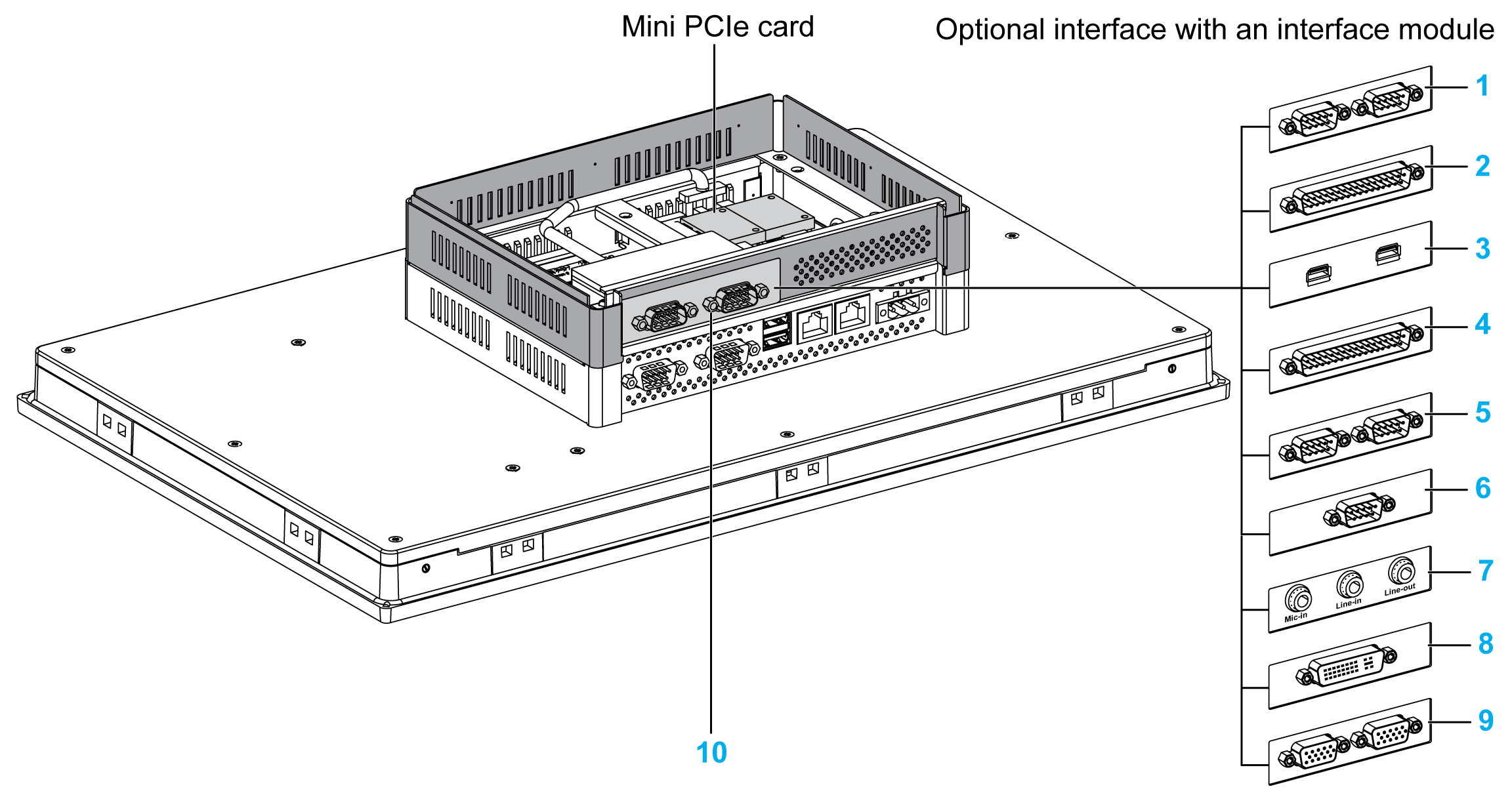
1 2 x RS-232/422/485 interface
2 4 x RS-232/422/485 interface
3 USB interface
4 DIO interface
5 CANopen interface
6 Profibus DP interface
7 Audio interface
8 DVI interface
9 VGA interface
10 Extension kit (HMIYPADPSOSTO1)
The table shows the type and the interface part numbers:
|
Designation |
Part number |
Interface |
PCIe card |
Pin header from system |
Interface plate |
|---|---|---|---|---|---|
|
HMIYMINNVRAM1 |
Card NVRAM |
1 |
– |
– |
|
|
HMIYMINSL24851 |
2 x RS-422/485 isolated |
1 |
– |
1 |
|
|
HMIYMINSL44851 |
4 x RS-422/485 |
||||
|
HMIYMINSL22321 |
2 x RS-232 isolated |
||||
|
HMIYMINSL42321 |
4 x RS-232 |
||||
|
HMIYMINIO1 |
16 x DI / 8 x DO |
1 |
– |
1 |
|
|
HMIYMINWIFI1 |
1 x Wireless LAN and 2 x antennas |
1 |
– |
1 |
|
|
HMIYMINGPRS1 |
1 x GPRS (general packet radio service) |
1 |
– |
1 |
|
|
HMIYMINCAN1 |
2 x CanOpen/CanBus |
1 |
– |
1 |
|
|
HMIYMINPRO1 |
1 x Profibus DP master NVRAM |
1 |
– |
1 |
|
|
HMIYMINUSB1 |
2 x USB 3.0 |
1 |
1 |
1 |
|
|
HMIYMINAUD21 |
1 x Audio |
1 |
– |
1 |
|
|
HMIYMINDVII1 |
1 x DVI-I |
1 |
– |
1 |
|
|
HMIYMINVGADVID1 |
1 x DVI-D |
1 |
– |
1 |
|
|
2 x VGA |
1 |
– |
1 |
||
|
HMIYMIN4GUS1 |
1 x 4G for US (general packet radio service) |
1 |
– |
1 |
|
|
HMIYMIN4GEU1 |
1 x 4G for UE/Asia (general packet radio service) |
1 |
– |
1 |
Before installing or removing a mini PCIe card, shut down Windows in an orderly fashion and remove the power from the device.
|
|
|
POTENTIAL FOR EXPLOSION IN HAZARDOUS LOCATION |
|
Do not use this product in hazardous locations. |
|
Failure to follow these instructions will result in death or serious injury. |
|
NOTICE |
|
ELECTROSTATIC DISCHARGE |
|
Take the necessary protective measures against electrostatic discharge before attempting to remove the Magelis Industrial PC cover. |
|
Failure to follow these instructions can result in equipment damage. |
NOTE: Be sure to remove the power before attempting this procedure.
|
Step |
Action |
|---|---|
|
1 |
Disconnect the power cord to the S-Panel PC. |
|
2 |
Touch the housing or ground connection (not the power supply) to discharge any electrostatic charge from your body. |
|
3 |
Remove the four screws of the rear cover: 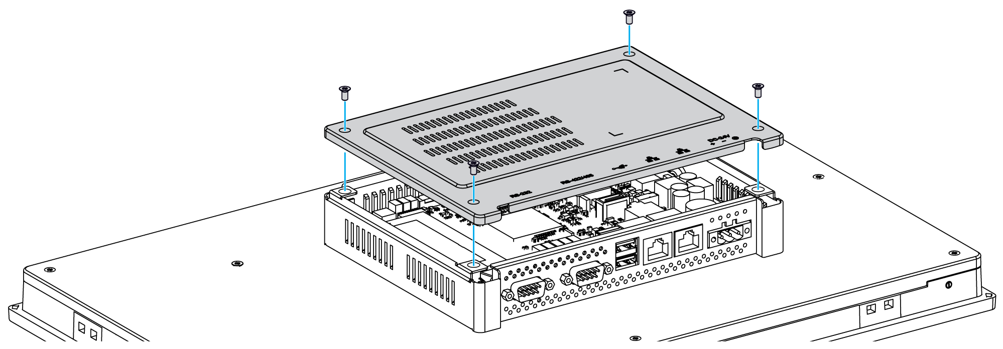
|
|
4 |
Install the mini PCIe card onto the board: 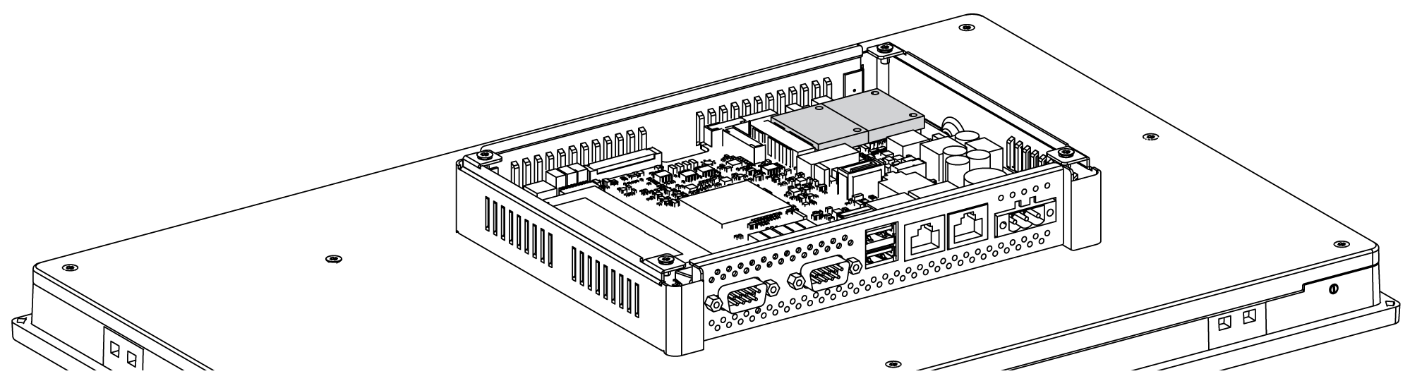
NOTE: The recommended torque to tighten these screws is 0.5 Nm (4.5 lb-in). |
|
5 |
Take out the extension kit (HMIYPADPSOSTO1), and remove the optional interface cover bracket. Install the interface onto the kit, using fasten screws on both sides of the interface: 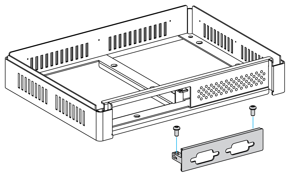
|
|
6 |
Connect the cable to the mini PCIe card that is on the motherboard: 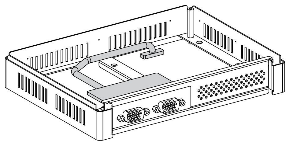
NOTE: When using a mini PCIe card with an external cable attached, use a clamp or a similar device to secure the cable. |
|
7 |
Fasten the extension kit to the S-Panel PC with the four studs: 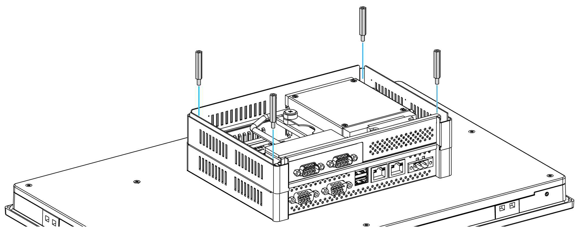
|
|
8 |
Replace the rear cover and fasten it with four screws: 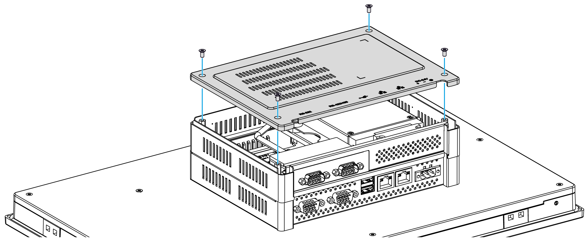
NOTE: The recommended torque to tighten these screws is 0.5 Nm (4.5 lb-in). |
|
|
|
OVERTORQUE AND LOOSE HARDWARE |
|
oDo not exert more than 0.5 Nm (4.5 lb-in) of torque when tightening the installation fastener, enclosure, accessory, or terminal block screws. Tightening the screws with excessive force can damage the installation fastener. oWhen fastening or removing screws, ensure that they do not fall inside the Magelis Industrial PC chassis. |
|
Failure to follow these instructions can result in injury or equipment damage. |


