Adding Functions from Template
Overview
You can add an application function from a function template by right-clicking a suitable node in a navigator and executing the command from the contextual menu.
Suitable nodes are:
-
An application node in the
-
A folder node below an application node in the
-
A controller node in the
-
A functional module node in the
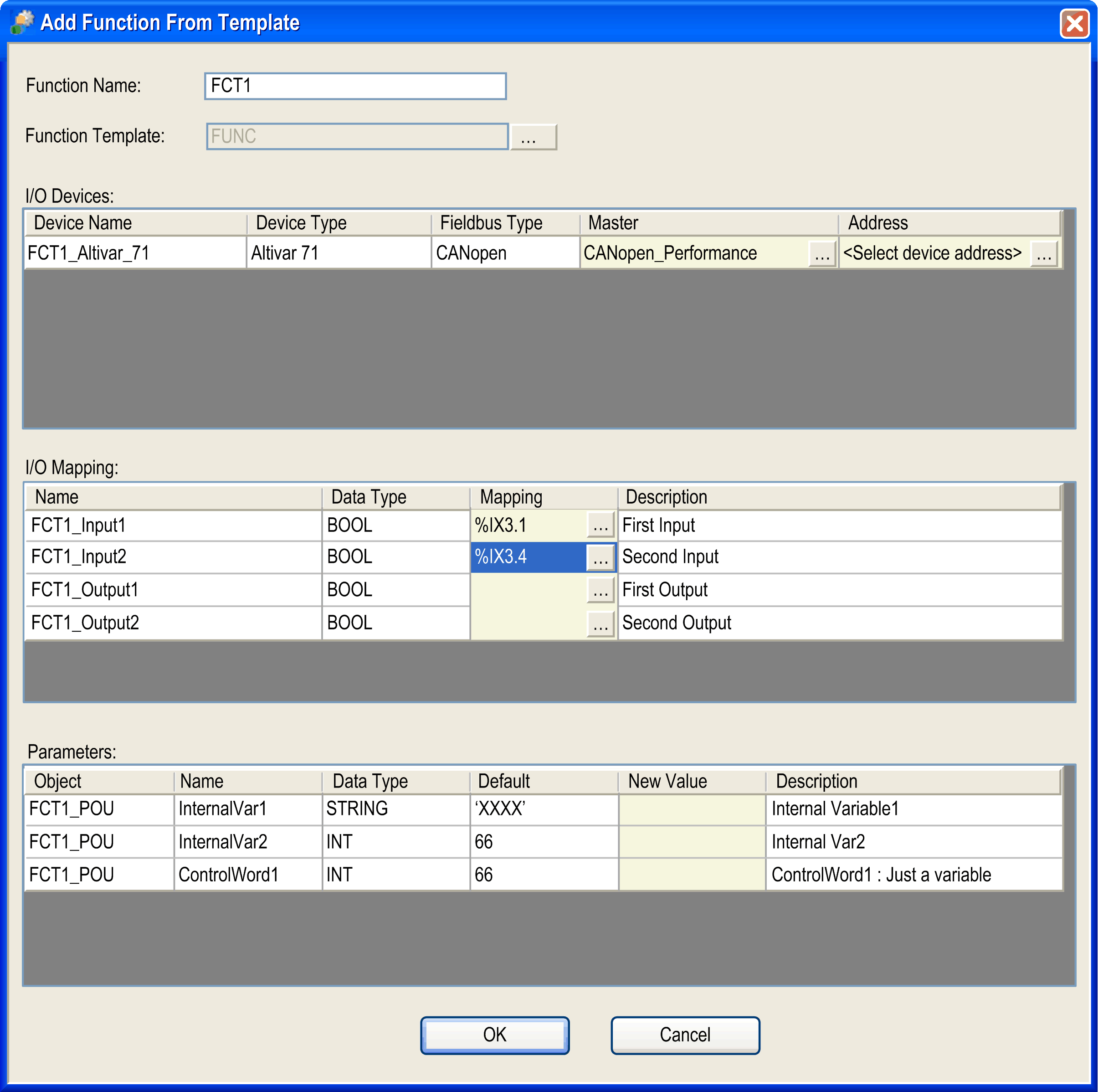
As a result, the dialog box opens.
Dialog Box

The dialog box provides the following elements to configure your function:
|
Element |
Description |
|
|---|---|---|
|
text box |
Enter a name that is used for the new folder of this application and for the naming of the elements it contains. |
|
|
|
Click the button and select a function template from the dialog box. |
|
|
table |
– |
|
|
|
Contains the name of the future field device. You cannot change this name. |
|
|
|
Indicates the type of the field device. You cannot edit this cell. |
|
|
|
Indicates the fieldbus type of the field device. You cannot edit this cell. |
|
|
|
Contains the fieldbus master to which the field device is connected. If there are several masters, you can select the master of your choice from the list. |
|
|
|
Initially empty. For field devices on fieldbusses that require numerical addresses (Modbus serial line and CANopen), click the button right to the field and assign the address of your choice. |
|
|
table |
Lists the I/O variables that are part of the function template. It allows you to map them to the I/O channels of existing devices and modules. |
|
|
|
Contains the name of the I/O variable that has to be mapped on an I/O channel. |
|
|
|
Indicates the data type of the I/O channel to which the I/O variable was originally mapped. |
|
|
|
Click the button to open the dialog box. It allows you to select an I/O channel on which you can map the selected variable. After the variable has been mapped to an I/O channel, this field contains the input or output address of the I/O channel on which the variable is mapped. |
|
|
|
Contains a description of the I/O variable. |
|
|
table |
Lists the template parameters included in the function template. |
|
|
|
Indicates the name of the GVL or program in which the variable is defined. You cannot edit this field. |
|
|
|
Contains the name of the variable. You cannot edit this cell. |
|
|
|
Indicates the data type of the variable. You cannot edit this cell. |
|
|
|
Indicates the default value of the variable. This is the initial value of the variable when the template was created. You cannot edit this cell. |
|
|
|
Edit this cell if you want to assign a new value to the variable. If you leave this cell empty, the value is used for this variable. Enter a value that is valid for the given data type. |
|
|
|
Contains a description of the variable. |
|
|
button |
Confirm your settings by clicking the button. Result: EcoStruxure Machine Expert verifies whether the settings are correct and inserts the new application function as separate node below the node or displays an error detection message. |
|
Dialog Box
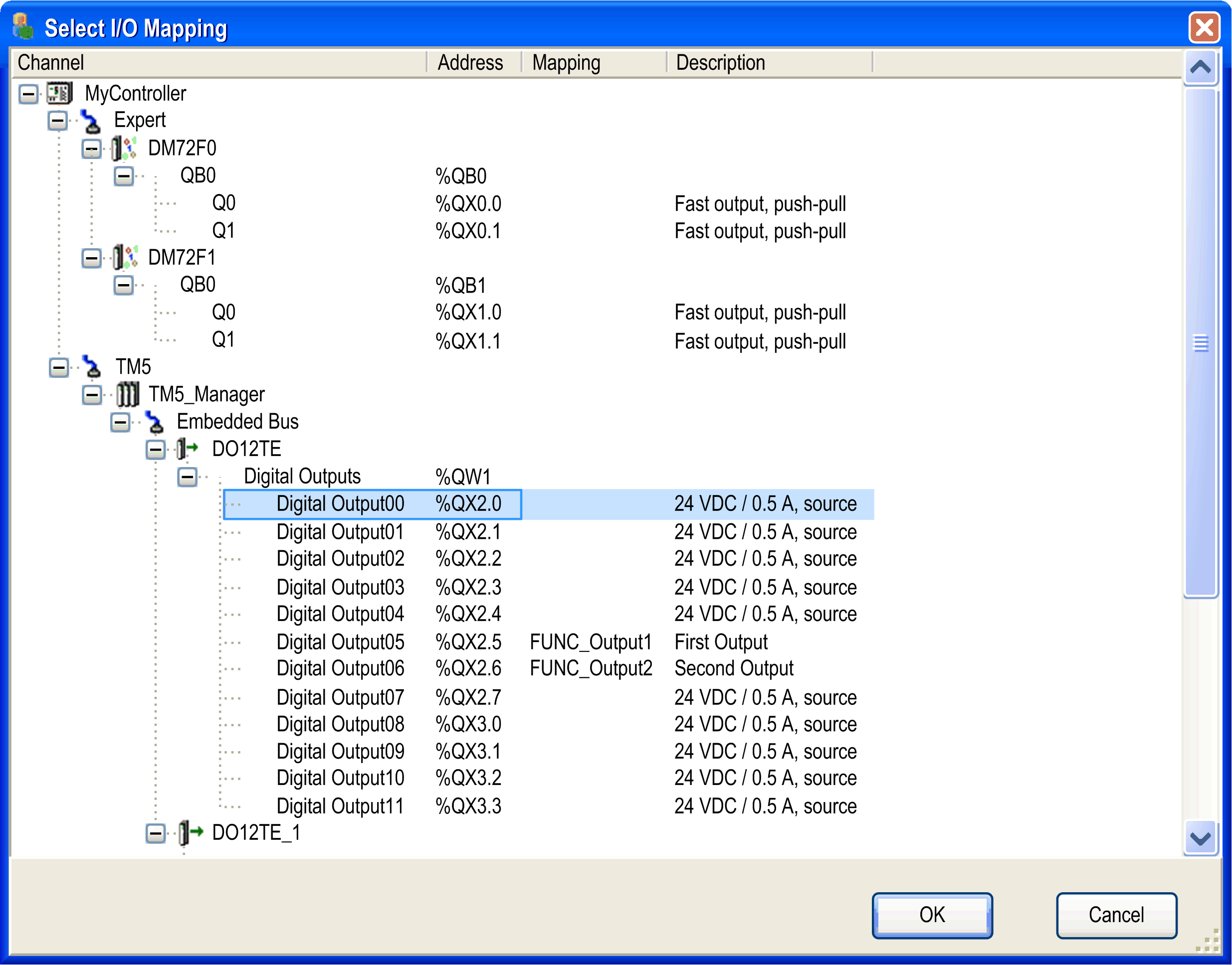
The dialog box is used to map a variable selected in the dialog box to an I/O channel.
It displays the available I/O channels in a tree structure, similar to the . The root node is the controller. Only those I/O channels are displayed whose data type fits to the data type of the new variable.
Two data types are compatible if they have identical type names or if they are elementary IEC data types of the same size.
Example:
UINT --> INT allowed
UDINT --> INT not allowed
Display the subnodes by clicking the plus signs.

The dialog box contains the following columns:
|
Column |
Description |
|---|---|
|
|
Contains the tree structure. Each device is represented by the device name and the device icon. Each I/O channel is represented by the channel name. |
|
|
Contains the input / output address that corresponds to the I/O channel. |
|
|
Contains the I/O variable that is currently mapped on the I/O channel. |
|
|
Contains the description of the I/O channel. |
Consider the following practices for mapping variables to I/O channels:
-
Map all variables provided by the function template to I/O channels.
-
You can map an I/O variable of a function template to an I/O channel that already has a mapping. The existing mapping is overwritten.
-
Any mappings that lead to multiple assignments of variables on the same I/O channel are not allowed.
Objects Created
The function template creates the following objects in your project:
|
Object |
Description |
|---|---|
|
Root folder |
A new folder is created under the node in the that is named as defined in the text box. |
|
Field devices |
The field devices that are included in the function template are created using names that apply to the naming rules and are connected to the fieldbus master. The I/O mapping is automatically adjusted, if necessary. |
|
Objects available as subnodes of the root folder in the navigators |
The objects that are included in the function template are created below the root folder in the respective navigator (, , ) using names that apply to the naming rules. The properties of the objects are automatically adjusted. |
|
Task configuration |
The task configuration is adjusted as required by the function template. |
|
Global variable lists |
The global variable lists that are included in the function template are created below the root folder using names that apply to the naming rules. |
|
External variables |
Global variables whose global variable lists do not belong to the function template are restored in their original global variable list as follows:
If the type of global variable is not correct, EcoStruxure Machine Expert issues an error detection message. |
|
Persistent variables |
Persistent variables are restored in the respective variable list of the application as follows:
If the type of persistent variable is not correct, EcoStruxure Machine Expert issues a message. |
|
External objects |
Objects that are not included in the function template but are referenced by the function template (such as function blocks and DUTs) are handled as follows:
|
Any objects that are created with the instantiation of the function template are listed in the pane.
Naming of Objects
In order to avoid naming conflicts, if you instantiate the same function template several times on the same controller device, the following naming conventions are applied to the application functions and the associated objects:
|
If the name of the original object... |
Then ... |
|---|---|
|
Case 1: |
|
|
contains the name of the application function, |
this part of the object is replaced by the name of the new application function that is created. |
|
Example: |
|
|
The template original application function |
For a new application function |
|
Case 2: |
|
|
does not contain the name of the application function, |
the name of the new application function plus an underscore are inserted in the original name to form a unique new name. |
|
Example: |
|
|
The original application function |
For a new application function |