Execution Order in CFC
Overview
The execution order of elements within POUs is uniquely determined in text-based and network-based editors. In the CFC editor, however, you can position the elements freely, so the execution order is initially not unique. Therefore, EcoStruxure Machine Expert determines the execution order by data flow and, in the case of multiple networks, by the topological position of the elements. The elements are sorted from top to bottom and from left to right to achieve a unique execution order.
The chronological order of the elements in the chart can be indicated in EcoStruxure Machine Expert by temporarily displaying the execution order. For networks with feedback, you can define an element as the starting point in the feedback loop.
EcoStruxure Machine Expert V2.0 and later versions allow you to edit the execution order in a CFC object explicitly by selecting the in the tab of the CFC object .
Data Flow
In general, the term data flow describes the chronological order of reading or writing which data when and how in which programming object. A POU can process an arbitrary number of data flows. These data flows can also be executed independently of each other.
Displaying the Execution Order
By default, the is selected in the tab of the CFC object and the execution order of a CFC object is determined automatically.
To temporarily display the execution order in the CFC editor, proceed as follows:
|
Step |
Action |
Comment |
|---|---|---|
|
1 |
Create a new project using the template and specify a name. |
Example name: |
|
2 |
Insert the function block |
Example: |
|
3 |
Create the function block ExecuteCFC in CFC implementation language. |
Example: 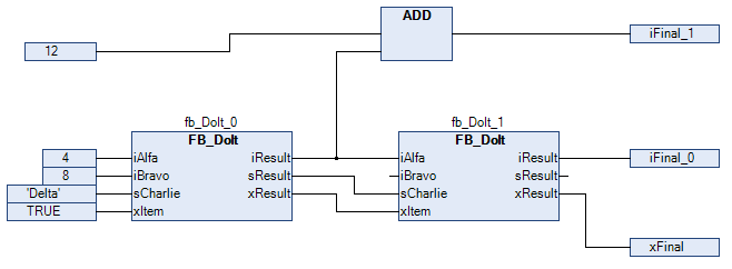
Programming objects recently created in CFC have selected the option . The optimum execution order of the programming objects is defined internally. |
|
4 |
Execute the command . |
Result: The execution order of the object is displayed: The boxes and inputs are numbered according to the chronological processing order. This temporary display is removed as soon as you click again in the CFC editor. |
Manually Determining the Execution Order in Feedback Networks
To manually determine the execution order in feedback networks, proceed as follows:
|
Step |
Action |
Comment |
|---|---|---|
|
1 |
Create a CFC program with feedback. |
Example: The POU 
|
|
2 |
Select an element within the feedback. |
Result: The selected element is highlighted red. |
|
3 |
Execute the command . |
Result: The selected element is assigned number 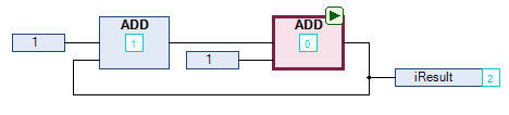
|
 symbol. At runtime, this POU is processed first.
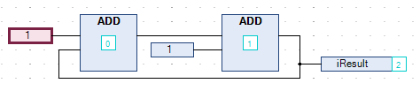
To undo this numbering, proceed as follows:
-
Select the POU defined as start POU.
-
Execute the command .
Result: The POU is no longer defined as start POU and the execution order is defined internally.
To display the execution order by data flow, execute the command .
Manually Defining the Execution Order
The default determines the order of CFC objects automatically to achieve execution that is optimized by time and by cycle. With this mode activated, you do not need to care for defining the execution order during the development process.
To manually define the execution order, proceed as follows:
|
Step |
Action |
Result |
|---|---|---|
|
1 |
In the or tree, right-click a CFC object and execute the command . |
The dialog box opens. |
|
2 |
Select the tab. |
The list displays the selected mode. |
|
3 |
From the list, select the option . |
– |
|
4 |
Click to confirm and to close the dialog box. |
|
|
5 |
Open a CFC object. |
– |
|
6 |
Select a numbered element and execute the command . |
The execution order is resorted and the selected element is assigned the number 0. |