TM5SE4IOL Presentation
Main Characteristics
|
Characteristic |
Value/description |
|
Power consumption of the module |
|
|
Number of input channels |
|
|
IO-Link |
IO-Link master |
|
Input type |
Refer to Characteristics. |
|
Input signal type |
Sink |
|
Output type |
Refer to Characteristics. |
|
Output signal type |
Source |
|
Output current |
0.25 A per channel |
|
Rated input voltage |
24 Vdc |
Ordering Information

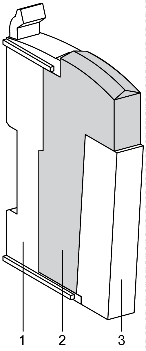
The following table lists the commercial references of the terminal blocks and the bus bases to be used with the IO-Link module TM5SE4IOL:
|
Number |
Commercial reference |
Description |
Color |
|---|---|---|---|
|
1 |
TM5ACBM11 |
Bus base |
White |
|
2 |
TM5SE4IOL |
Electronic module |
White |
|
3 |
TM5ACTB12 |
Terminal block, 12 pins |
White |
Status LEDs
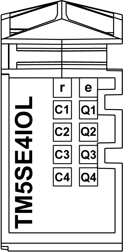
Status LEDs of the IO-Link module TM5SE4IOL:

The following table explains the status LEDs of the IO-Link module TM5SE4IOL:
|
LED |
Color |
Status |
Description |
|---|---|---|---|
|
r |
Green |
Off |
No power supply |
|
Single flash |
Reset state |
||
|
Flashing |
Preoperational state |
||
|
Double flash |
Boot state (during firmware update)1 |
||
|
On |
Regular operation |
||
|
e |
Red |
Off |
OK or no power supply |
|
On |
Error detected or reset state |
||
|
Double flash |
Internal errror detected |
||
|
C1 - C4 |
Red |
On |
Overcurrent/short circuit on the supply or on the C/Q line of the channel |
|
Green/Red |
Off |
Interface in SIO (Standard Input Output) |
|
|
Single flash |
Channel in Operate mode, no IO-Link communication |
||
|
Double flash |
Channel in Operate mode, inspection level error detected. |
||
|
Green |
On |
Channel in Operate mode, IO-Link communication active |
|
|
Q1 - Q4 |
Orange |
- |
Input/output state of corresponding IO-Link interface |
|
(1) Depending on the configuration, a firmware update can take up to several minutes. |
|||