Graphical Editor
The graphical editor is located in the lower part of the CNC tabular editor and the editor for DIN 66025. The editor is used for visualizing the programmed CNC program.
The editor provides easy tools for modifying and extending the path.
Structure of the editor
-
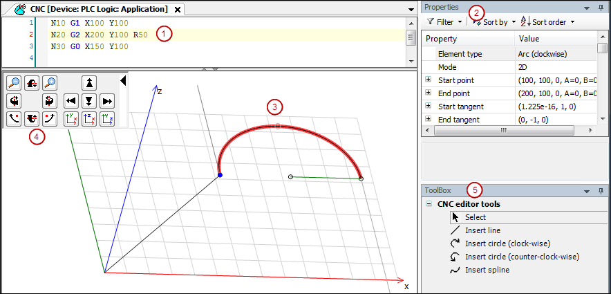
(1): Tabular editor or editor according to DIN 66025
-
(2): Properties view: Shows the properties of the selected path element
-
(3): Graphical editor
-
(4): Control panel: Elements for controlling the camera position and viewing direction
-
(5): Tools for modifying the path
Notes about working with the graphical editor
-
The selected path element is displayed in red.
-
Positioning commands (G0) and switch point functions are displayed in green.
-
If the end point of an element is movable, then it is displayed as a small black outlined circle.
-
Start and end tangents are displayed in gray.
-
The current position of the selected path element is displayed in the status bar.
Please note the CNC menu commands for scaling and moving the entire path.
Please note the sample programs included in the installation of CODESYS SoftMotion.
Tools
You can use tools to modify and extend motion paths in the graphical editor. The changes are visible simultaneously in the text editor and tabular editor.
|
|
Select: This tool selects a point or a path element. The element is then displayed in red with a blue start point. The mouse pointer in the graphical editor changes into a pointer. |
|
|
Line: Adds or inserts a new line. The mouse pointer in the graphical editor changes into a cross. |
|
|
Insert circle (clockwise): Adds or inserts a new arc (clockwise). The mouse pointer in the graphical editor changes into a cross. |
|
|
Insert circle (counterclockwise): Adds or inserts a new arc (counterclockwise). The mouse pointer in the graphical editor changes into a cross. |
|
|
Spline: Adds or inserts a new spline point. The mouse pointer in the graphical editor changes into a cross. |
See also
Camera position and viewing direction
You can use the mouse to modify the position and camera perspective on the program path in any way.
-
Left mouse button pressed + mouse movement: Moves the camera position along the axes in the display plane.
-
Right mouse button pressed + mouse movement: Rotates the view on the CNC program.
-
Ctrl pressed + Mouse wheel: Changes the zoom factor.
Operating panel for display control
In the upper left corner of the graphical editor, an operating panel provides various commands for changing the view of the path. The path is not modified in the process. Instead, only the camera position and camera perspective are changed.
You can collapse the control panel by clicking the black arrow in order to maximize the size of the editor workspace. Clicking again expands the control panel.
The control panel provides the following commands for setting the orientation, position, and zoom.
|
|
Zoom in |
|
|
Zoom out |
|
|
Change the camera pitch (clockwise) |
|
|
Change the camera pitch (counterclockwise) |
|
|
Change the camera yaw (clockwise) |
|
|
Change the camera yaw (counterclockwise) |
|
|
Rotate the camera (clockwise) |
|
|
Rotate the camera (counterclockwise) |
|
|
Move camera upwards |
|
|
Move camera to the left |
|
|
Move camera to the right |
|
|
Move camera downwards |
|
|
Set the direction of view to the negative z-axis and rescale |
|
|
Set the direction of view to the x-axis and rescale |
|
|
Set the direction of view to the y-axis and rescale |