Parallel Kinematics
Tripod with linear axes
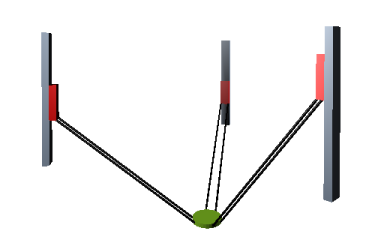
This system has three linear drives that are in a defined angle to each other. The drives consist of 3 rails with traversing slides. The tool plate is connected to the traversing slides by connecting rods of the same length. A paired set of connecting rods holds the tool plate parallel to the floor in the same orientation. The kinematics can move the tool plate in three dimensions.
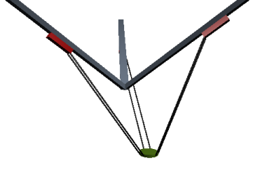
The forward and inverse transformation of these kinematics is calculated in the POUs SMC_Trafo_Tripod_Lin and SMC_TrafoF_Tripod_Lin. The axis angle of the tripod is defined by the angle between the rail and the vertical axis (dAxisAngle).
Mechanical requirements and coordinate system
-
The lengths of the 3 axes are identical.
-
The lengths of the connecting rods are identical.
-
The distance between the pairs of connecting rods to each other is identical for all pairs.
-
The axis angle between drive rails and the vertical axis is identical for all three drives. The angle allowance is between 0° and 90°.
-
The axis defines the movement of the point between the connecting rod joints on the sliders.
-
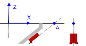
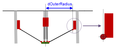
The XYZ coordinate system is right-handed. The X and Y vectors are horizontal and Z points up. The origin is defined so that the intersections of the three movement axes with the XY plane (graphics below - points A) is on a circle at position [0,0,0].
|
Name |
Description |
|---|---|
|
|
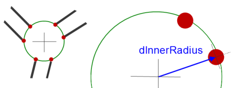
Distance from the center of the tool plate to the gripping points of the connecting rods
|
|
|
|
|
|
Length of the connecting rods |
|
|
Distance between the two connecting rods in one pair |
|
|
Point A of the first axis defines the X-axis by default. The offset is used to rotate the entire structure about the Z-axis. In this case, point A is no longer on the X-axis.
|
|
|
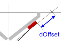
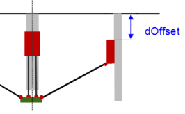
The offset is used to set the positional value of the axis to its default setting of zero.
|
|
|
|
|
|
|
|
You will find information about other parameters in the library description. |
|

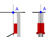
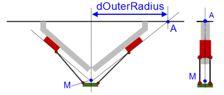 Point A is the intersection of the axis with the XY plane.
See also
Tripod with vertical axes
This system is a special variant of the kinematic design described above and has the same mechanical requirements. The angle dAxisAngle between the guide rails and the vertical axis is 0° and the guide rails are parallel to the vertical axis.
The forward and inverse transformation of these kinematics is calculated in the POUs SMC_Trafo_Tripod_Lin and SMC_TrafoF_Tripod_Lin. The axis angle of the tripod is defined by the angle between the rail and the vertical axis (dAxisAngle).
|
Name |
Description |
|---|---|
|
|
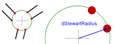
The parameter defines the radius of the circle that is described by the six gripping points of the connecting rods to the tool plate.
|
|
|
|
|
|
Length of the connecting rods |
|
|
Distance of the pairs of connecting rods to each other |
|
|
Point A of the first axis defines the X-axis by default. The offset is used to rotate the entire structure about the Z-axis. In this case, point A is no longer on the X-axis.
|
|
|
The offset is used to set the positional value of the axis to its default setting of zero.
|
|
|
|
|
|
|
|
You will find information about other parameters in the library description. |
|
See also
Tripod with rotary axes
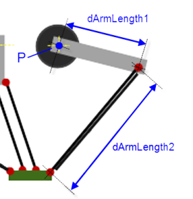
For tripods, the kinematics are implemented by 3 rotary drives that are connected to the tool plate by arms and connecting rods.
The origin of the coordinate system is the location of the center of the tool plate when all 3 arms are in a horizontal position.
The forward and inverse transformation of these kinematics is calculated in the POUs SMC_TRAFO_Tripod_Arm and SMC_TRAFOF_Tripod_Arm.
Mechanical requirements and coordinate system
-
The lengths of the three axes are identical.
-
The lengths of the connecting rods are identical.
-
The distance between the pairs of connecting rods to each other is identical for all pairs.
|
Name |
Description |
|---|---|
|
|
|
|
|
|
|
|
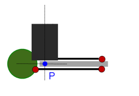
The parameter defines the radius of the circle that is established by the 3 points P of the drives.
|
|
|
The parameter defines the radius of the circle that is described by the 6 gripping points of the connecting rods to the tool plate.
|
|
|
Distance between the two connecting rods in one pair |
|
|
|
|
|
|
|
|
|
|
You will find information about other parameters in the library description. |
|
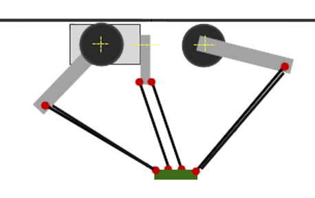
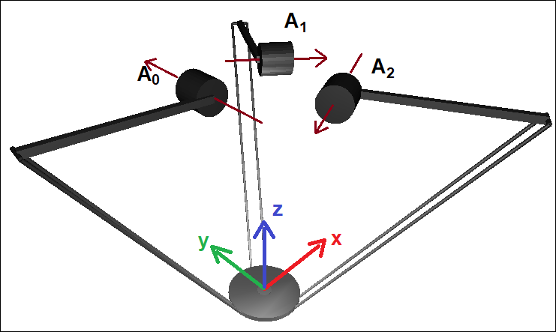
The image shows the zero position of all axes. (The three upper arms are horizontal.) The MCS is shown at the tool plate. The arows on the A0, A1, and A2 axes show the direction of rotation of the drives according to the right-hand rule.
|
Machine Coordinate System (MCS) |
|
|
Origin |
Defined in the midpoint of the tool plate when all 3 upper arms (those that are connected directly with A0, A1, or A2) are in a horizontal position. |
|
X |
From the origin, points away from the first motor (A0), parallel to the upper arm segment of the first arm. |
|
Y |
Determined by X and Z so that the MCS is right-handed. |
|
Z |
Orthogonal to the tool plate. Points from the tool plate in the direction of the motors. |
The respective transformations are executed by the following POUs SMC_TRAFO_Tripod_Arm and SMC_TRAFOF_Tripod_Arm:
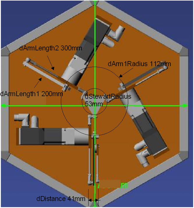
Example: 3S tripod
Transformation settings
tta:
SMC_TRAFO_Tripod_Arm := (dArmLength1:=200, dArmLength2:=300, dArm1Radius:=112, dStewartRadius:=53,dDistance:=41,dMaxAngleBallJoint:=60);
ttaf:
SMC_TRAFOF_Tripod_Arm := (dArmLength1:=200, dArmLength2:=300, dArm1Radius:=112, dStewartRadius:=53,dDistance:=41);
See also