6-Axis Articulated Robot
Transformation of an articulated arm robot with six rotary axes and six degrees of freedom (DoF). The three orientation axes of the robot arm intersect at one point: the joint center.
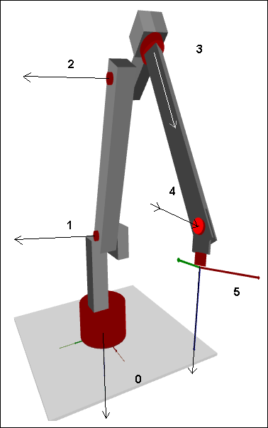
The function blocks SMC_Trafo_ArticulatedRobot_6DOF and SMC_TrafoF_ArticulatedRobot_6DOF implement forward and inverse transformations of an articulated arm robot with six rotational axes. In the image, the Cartesian coordinate system is marked below at axis 0. The Z axis points downwards and the X axis points forwards in the direction of the tool center point (TCP). The origin of the Cartesian coordinate system is the intersection axis 0 and the underside of the robot.
Definition of axes
The rotary axes are marked with black arrows. The positive rotational direction results from the right-hand rule. For example, if axis 0 rotates in the positive direction, then the robot rotates clockwise as viewed from above.
The axes are restricted to the following ranges:
-
Axes 0, 1, 3, and 4: ]-180°, 180°[
-
Axis 2: [-90°, 180°]
-
Axis 5: Unrestricted; the range can be greater than 360°.
Homing position and dimensions
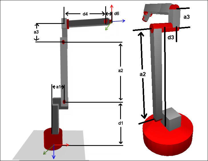
The image on the left shows the homing position of the kinematics, which is the position where all axes are in their zero position. Specify the indicated dimensions in the configuration structure SMC_TrafoConfig_ArticulatedRobot_6DOF. The names and signs of the parameters are in accordance with the Denavit–Hartenberg convention. The image on the right shows the additional Denavit–Hartenberg parameter d3.
Please note:
-
a1, a3, d4, d6 must be >= 0
-
a2 must be >0 (>
g_fSMC_CNC_EPS) -
d1 must be <= 0