PROFIBUS DP - Bus Cycle Task
General information
As a rule, for each IEC task the used input data is read at the start of each task (1) and the written output data is transferred to the I/O driver at the end of the task (3). The implementation in the I/O driver is decisive for further transfer of the I/O data. The implementation is therefore responsible for the timeframe and the specific time when the actual transmission occurs on the respective bus system.
The bus cycle task of the PLC can be defined globally for all fieldbuses in the PLC settings. For some fieldbuses, however, you can change this independent of the global setting. The task with the shortest cycle time is used as the bus cycle task (setting: unspecified in the PLC settings). In this task, the messages are normally transferred on the bus.
Other tasks copy only the I/O data from an internal buffer that is exchanged only with the physical hardware in the bus cycle task.
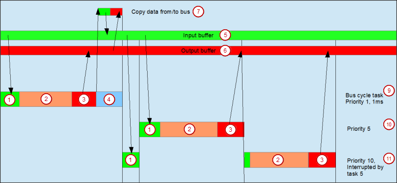
(1) Read inputs from input buffer       (2) IEC task
(3) Write outputs to output buffer      (4) Bus cycle
(5) Input buffer                        (6) Output buffer
(7) Copy data to/from bus
(9) Bus cycle task, priority 1, 1 ms
(10) Bus cycle task, priority 5
(11) Bus cycle task, priority 10, interrupted by task 5
Using tasks
The Task Deployment provides an overview of used I/O channels, the set bus cycle task, and the usage of channels.
| WARNING | |
|---|---|
PROFIBUS DP does not provide any additional settings. Its functionality corresponds to the general description.
See also