Getting Started - Commissioning NetX Adapters
Requirement: A netX adapter is inserted into a slot of the computer.
1. Installing drivers for Windows
If you want to use a NetX adapter with a CODESYS runtime system, then you must install the following drivers:
-
For CODESYS Control Win V3: Driver
SysDrv3s.sys -
For CODESYS Control RTE V3: Driver
RTIOwdmGenericc.sysorSysDrv3s.sysNote: The installed driver must be passive. When using CODESYS Control RTE V3, it is also possible to install no specific driver at all.
When installing CODESYS Control Win V3, the driver SysDrv3s.sys is saved in the program folder ../GatewayPLC/Driver; for CODESYS Control RTE V3, in the ../SysDrv3s folder.
The NetX firmware and the NetX boot loader are located in the HilscherCIFX folder for both runtime systems.
The NetX firmware and the NetX Second Stage Boot Loader must be the same version. Otherwise, the NetX firmware and the fieldbus will not work.
The NetX Second Stage Boot Loader and the NetX firmware are reloaded to the NetX chip each time the runtime system is started.
2. Editing the file "CODESYSControl.cfg" in the CODESYS runtime system folder
-
Open the file
CODESYSControl.cfgof the respective runtime system directory in a text editor. -
Remove the semicolon in the section
[ComponentManager]at the beginning of the entryCmpHilscherCIFXso that the entry is no longer commented out. -
In the area
[CmpHilscherCIFX], follow the steps below to edit the entries for the NetX adapter and the NetX configuration.The following entries must exist for the firmware and boot loader:
DynamicFirmware=1BootloaderFile=./HilscherCIFX/Firmware/NETX100-BSL.binFirmwareFilePath=./HilscherCIFX/Firmware -
If the entry
DMAMode=1is commented out, then remove the semicolon (;) at the beginning of the line. -
Remove the semicolon in front of the following entries:
Device.0.BootloaderFilePath=.\\HilscherCIFX\\Firmware\\NETX100-BSL.binDevice.0.Channel.0.FirmwareFile=.\\.\\HilscherCIFX\\Firmware\\cifxcom.nxfDescription:
-
Device.X.BootloaderFilePath: Specifies the file path and the file name of the NetX boot loader for each NetX chip. (The relative path starts in the installation folder. Absolute paths are also possible.) If multiple NetX chips are used, the multiple files paths must also be specified:Device.0.BootloaderFilePath=.\\HilscherCIFX\\Firmware\\NETX100-BSL.binDevice.1.BootloaderFilePath=.\\HilscherCIFX\\Firmware\\NETX100-BSL.bin -
Device.X.Channel.X.FirmwareFile: Specifies the file path and the file name of the NetX firmware for each NetX chip and each channel. (The relative path starts in the installation folder. Absolute paths are also possible.) In most cases, only channel 0 is used. If multiple NetX chips are used, the multiple files paths must also be specified:Device.0.Channel.0.FirmwareFile=.\\HilscherCIFX\\Firmware\\cifxcom.nxfDevice.1.Channel.0.FirmwareFile=.\\HilscherCIFX\\Firmware\\cifxcom.nxf
-
-
If you want to receive more comprehensive logger messages from your controller (device editor of the controller, Log tab), then remove the semicolon (
;) at the following locations: in the area[CmpHilscherCIFX]before the entryTraceLevel=0xffffffff, and in the area[CmpLog]before the entries:Logger.0.Name=PlcLogLogger.0.Filter=0xFFFFFFFF -
Save the file
CODESYSControl.cfg.
3. Creating a NetX configuration for a project
-
Create a new standard project in CODESYS by clicking . In the New Project dialog, select the Standard project template.
-
In Standard Dialog, select the controller (example: CODESYS Control Win V3) and click OK.
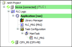
⇒ The new standard project is displayed in the device tree.
-
Click Add Device in the context menu of the controller.
-
In the Add Device dialog of , select a NetX fieldbus master (example: CIFX-PB) and click Add Device.
-
Double-click the NetX fieldbus master in the device tree (example: CIFX-PB) and select the NetX Configuration tab in the editor.
-
Select Slot 0 from the Slot drop-down list and NetXComChannel0 from NetX com channel .
Caution: The number of the selected slot (example: Slot 0) must correspond to the number of the device in the file
CODESYSControl.cfg(example:Device.0). Likewise, the number of the selected NetX com channel (example: NetX com channel 0) must correspond to the entries in the fileCODESYSControl.cfg(example:Channel.0). -
Build the project, log into the controller, and start the application by clicking .
⇒
If there are no error messages, then the NetX adapter has been configured correctly and you can now continue developing the project.
See also