This module is fitted with a removable screw terminal block for the connection of digital inputs and digital outputs.
|
|
|
FIRE HAZARD |
|
oUse only the correct wire sizes for the current capacity of the I/O channels and power supplies. oFor relay output (2 A) wiring, use conductors of at least 0.5 mm2 (AWG 20) with a temperature rating of at least 80 °C (176 °F). oFor common conductors of relay output wiring (4 A), or relay output wiring greater than 2 A, use conductors of at least 1.0 mm2 (AWG 16) with a temperature rating of at least 80 °C (176 °F). |
|
Failure to follow these instructions will result in death or serious injury. |
There are several rules that must be followed when wiring a TM2...N I/O expansion module.
For modules that have more than one terminal block or connector that is identical, any of them can be potentially plugged into any socket.
Despite the indicators on the terminal blocks, connectors, and modules, it is possible to incorrectly install the terminal blocks or connectors and create incorrect wiring.
Plugging a connector into the wrong socket could cause unintended behavior of the application.
|
|
|
ELECTRIC SHOCK OR UNINTENDED EQUIPMENT OPERATION |
|
Connect the terminal blocks to their designated location. |
|
Failure to follow these instructions will result in death or serious injury. |
|
|
|
UNINTENDED EQUIPMENT OPERATION |
|
Do not exceed any of the rated values specified in the environmental and electrical characteristics tables. |
|
Failure to follow these instructions can result in death, serious injury, or equipment damage. |
The table below shows the characteristics of the removable screw terminal blocks:
|
Characteristic |
Description |
|
|---|---|---|
|
Type of terminal blocks |
Removable screw terminal blocks |
|
|
Number of wires accommodated |
1 |
|
|
Wire gauges accommodated |
minimum |
0.5 mm2 (20 AWG) |
|
maximum |
1.5 mm2 (14 AWG) |
|
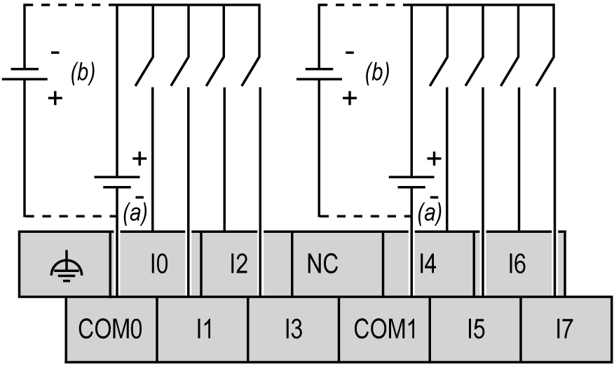
The following figure shows the input terminal block connections of the TM2DMM16DRTN to the sensors:

a Sink wiring (positive logic)
b Source wiring (negative logic)
NC Not Connected (N.C.)
NOTE: Both sink and source input wiring are supported.
NOTE: The COM0 and COM1 terminals are not connected together internally.
|
|
|
UNINTENDED EQUIPMENT OPERATION |
|
Do not connect wires to unused terminals and/or terminals indicated as “No Connection (N.C.)”. |
|
Failure to follow these instructions can result in death, serious injury, or equipment damage. |
The following figure shows the output terminal block connections of the TM2DMM16DRTN to the relay output:

1 Protection for inductive load
NOTE: Connect an appropriate fuse for the load, not to exceed 2 A on the outputs and 4 A on the output power supply.
NOTE: The COM0, COM1 and COM2 terminals are not connected together internally.
For more information, refer to the TM2...N System Wiring Rules and Recommendation.