The following controllers are equipped with an Ethernet communications port:
oTM218LDAE24DRHN
oTM218LDAE40DRPHN
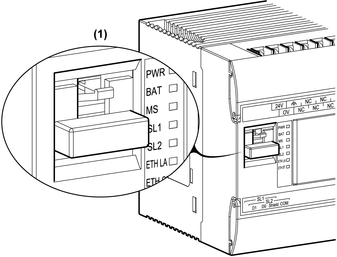
The following illustration shows the location of the Ethernet port on the controller:

(1) Ethernet port with dust plug
The table below describes the different Ethernet characteristics:
|
Characteristic |
Description |
|---|---|
|
Function |
EcoStruxure Machine Expert Protocol |
|
Connector type |
|
|
Driver |
o10 M half duplex (auto negotiation) o100 M full duplex (auto negotiation) |
|
Cable type |
Shielded |
|
Automatic cross-over detection |
Yes |
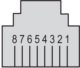
The following illustration shows the RJ45 Ethernet connector pin assignment:

The table below describes the RJ45 Ethernet connector pins:
|
Pin N° |
Signal |
|---|---|
|
1 |
TD+ |
|
2 |
TD- |
|
3 |
RD+ |
|
4 |
- |
|
5 |
- |
|
6 |
RD- |
|
7 |
- |
|
8 |
- |
NOTE: The controller supports the MDI/MDIX auto-crossover cable function. It is not necessary to use special Ethernet crossover cables to connect devices directly to this port (connections without an Ethernet hub or switch).

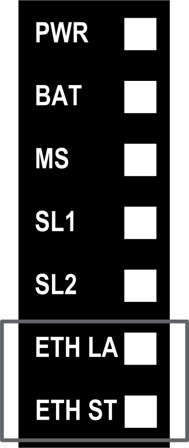
The table below describes the ETH LA and ETH ST Ethernet status LEDs:
|
Label |
Description |
LED |
||
|---|---|---|---|---|
|
Color |
Status |
Description |
||
|
ETH LA |
Ethernet Activity |
Green/Yellow |
Off |
No link |
|
Green on |
Link at 100 Mbps |
|||
|
Yellow on |
Link at 10 Mbps |
|||
|
Green flash |
Activity at 100 Mbps |
|||
|
Yellow flash |
Activity at 10 Mbps |
|||
|
ETH ST |
Ethernet Status |
Green |
Off |
Physical connections are unplugged and no IP address is obtained. |
|
Green on |
Minimum one port is connected and an IP address is obtained |
|||
|
3 green flashes |
All the ports are unplugged, but the card has an IP address. |
|||
|
4 green flashes |
Duplicated IP address is detected. |
|||
|
5 green flashes |
||||
|
6 green flashes |
The configured IP is invalid using default IP. |
|||