The Modbus IOScanner is used to simplify exchanges with Modbus slave devices.
|
Step |
Action |
|---|---|
|
1 |
In the Devices tree, delete Machine_Expert_Network_Manager or Modbus_Manager from the Serial Line x node if any. |
|
2 |
Select the Modbus IOScanner in the Hardware Catalog, drag it to the Devices tree, and drop it on one of the highlighted nodes. |
To configure a Modbus IOScanner on Serial Line, proceed as follows:
|
Step |
Action |
|---|---|
|
1 |
In the Devices tree, double-click Modbus IOScanner. Result: The configuration window is displayed. |
Set the parameters as described in the following table:
|
Element |
Description |
|---|---|
|
Transmission Mode |
Specify the transmission mode to use: oRTU: uses binary coding and CRC error-checking (8 data bits) oASCII: messages are in a ASCII format, LRC error-checking (7 data bits) This parameter must be identical for each Modbus device on the link. |
|
Response Timeout (ms) |
Timeout used in the exchanges. |
|
Time between frames (ms) |
Time to avoid bus-collision. This parameter must be identical for each Modbus device on the link. |
NOTE:
oIf a configured Modbus slave does not answer correctly to 5 consecutive requests, this slave is set in an error state in EcoStruxure Machine Expert and no more requests are sent to it until the next warm or cold reset.
oDo not use function blocks of the PLCCommunication library on a serial line with a Modbus IOScanner configured. This disrupts the Modbus IOScanner exchange.
Adding a Device on the Modbus IOScanner
To add a device on the Modbus IOScanner, select the Generic Modbus Slave in the Hardware Catalog , drag it to the Devices tree, and drop it on the Modbus_IOScanner.
Configuring a Device Added on the Modbus IOScanner
To configure the device added on the Modbus IOScanner, proceed as follows:
|
Step |
Action |
|---|---|
|
1 |
In the Devices tree, double-click Generic Modbus Slave. Result: The configuration window is displayed. 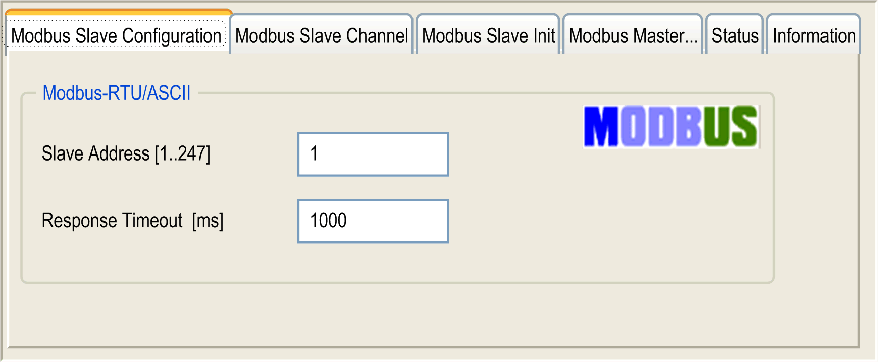
|
|
3 |
Enter a Slave Address value for your device (choose a value from 1 to 247). |
|
4 |
Choose a value for the Response Timeout (in ms). |
To configure the Modbus Channels, proceed as follows:
|
Step |
Action |
|---|---|
|
1 |
Click the Modbus Slave Channel tab. 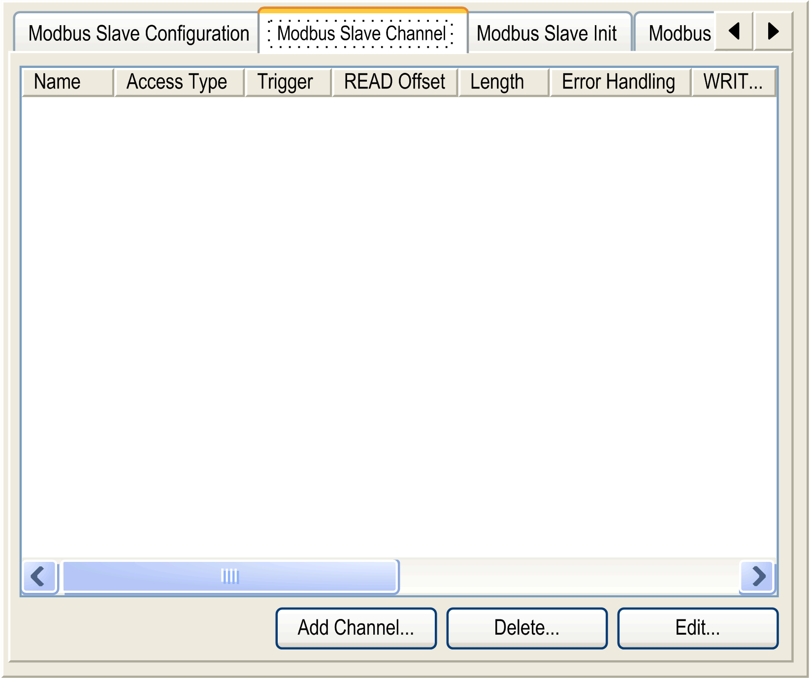
|
|
2 |
To configure an exchange, click the Add Channel button: 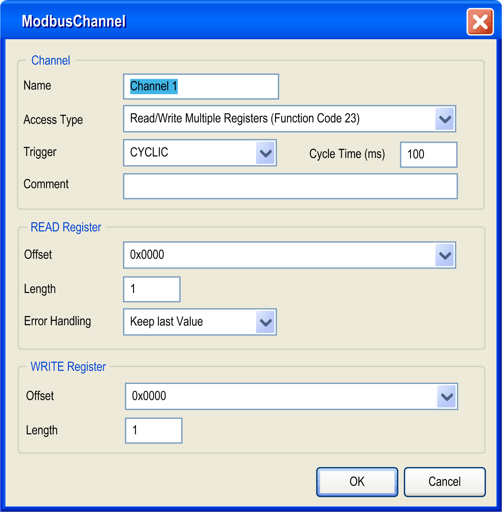
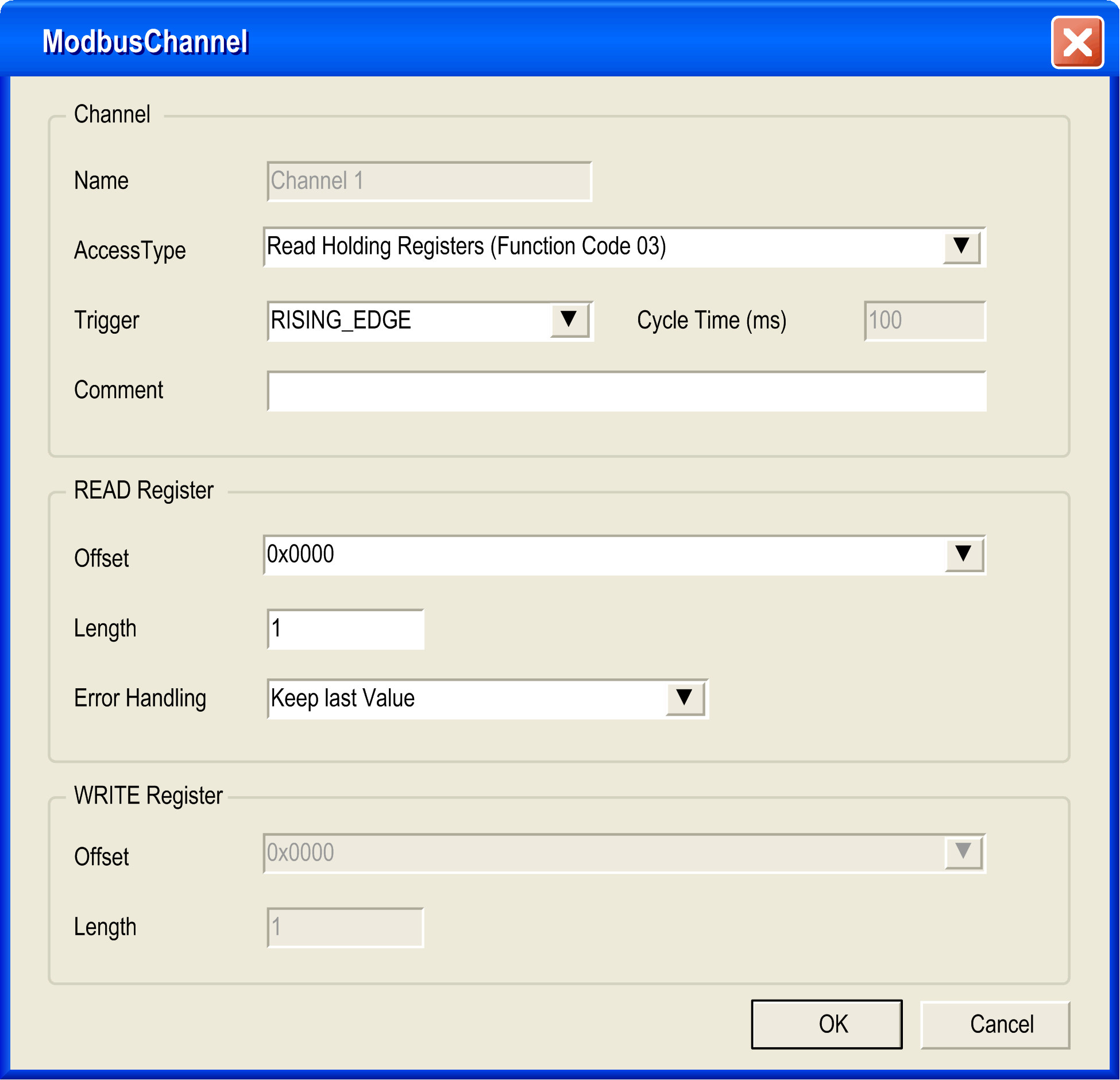
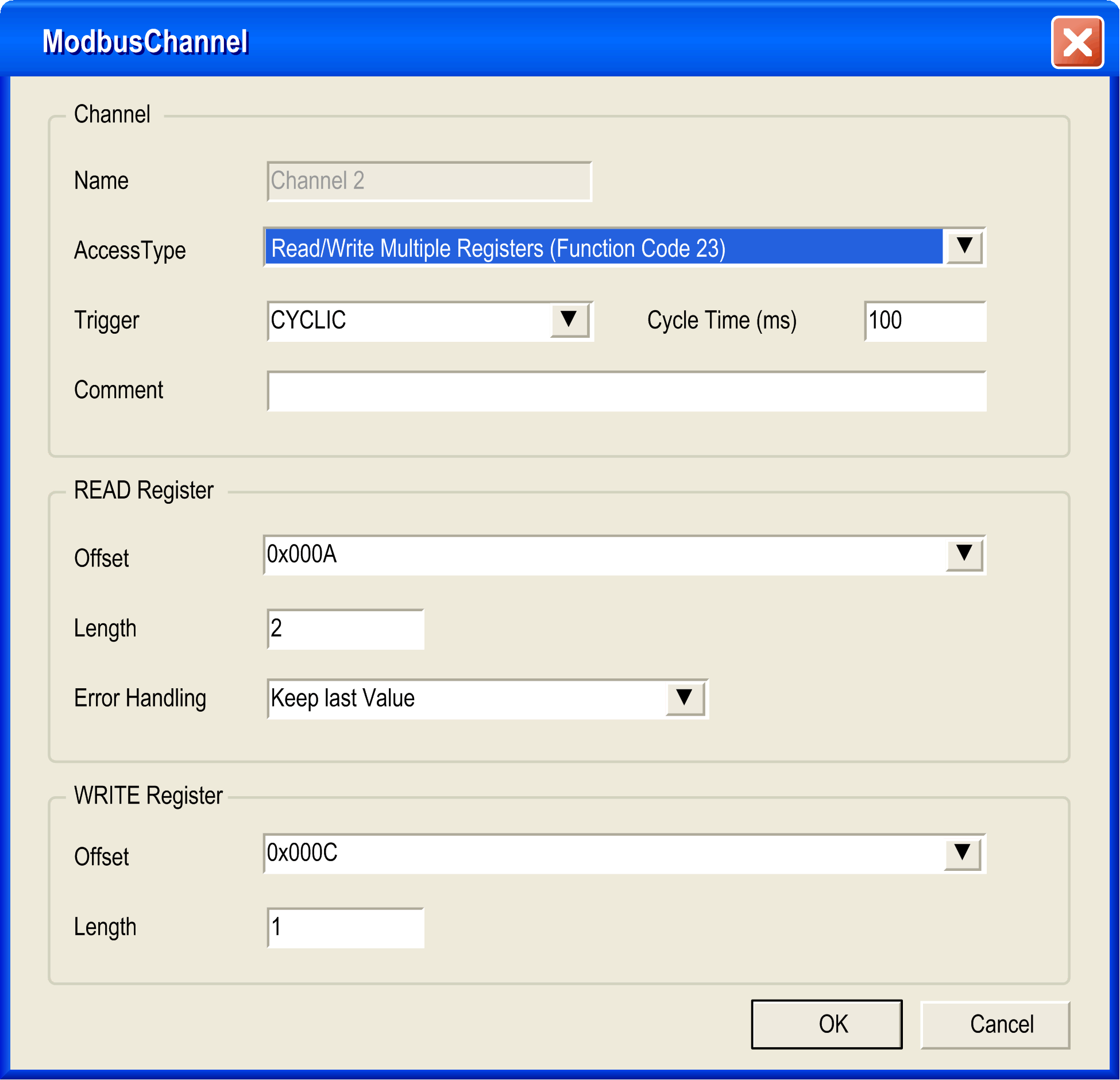
In the field Channel, you can add the following values: oName: Enter a name for your channel oAccess Type: Read or Write or Read/Write multiple registers. oTrigger: Choose the trigger of the exchange. It can be either CYCLIC with the period defined in Cycle Time (ms) field or started by a RISING EDGE on a boolean variable (this boolean variable is then created in the Modbus Master I/O Mapping tab) oComment: Add a comment about this channel |
|
2 bis |
In the field READ Register (if your channel is a Read or a Read/Write one), you can configure the %MW to be read on the Modbus slave. Those addresses will be mapped on %IW (see Modbus Master I/O Mapping tab): oOffset: Offset of the %MW to read. 0 means that the first object that will be read will be %MW0. oLength: Number of %MW to be read. For example if Offset = 2 and Length = 3, the channel will read %MW2, %MW3 and %MW4. oError Handling: choose the behavior of the related %IW in case of loss of communication. In the field WRITE Register (if your channel is a Write or a Read/Write one), you can configure the %MW to be written to the Modbus slave. Those addresses will be mapped on %QW (see 'Modbus Master I/O Mapping' tab): oOffset of the %MW to write. 0 means that the first object that will be written will be %MW0. oLength: Number of %MW to be written. For example if Offset = 2 and Length = 3, the channel will write %MW2, %MW3 and %MW4. |
|
3 |
Click the Delete button to remove a channel. Click the Edit button to change the parameters of a channel. |
|
4 |
Click OK to validate the configuration of this channel. |
To configure your Modbus Initialization Value, proceed as follows:
|
Step |
Action |
|---|---|
|
1 |
Click the Modbus Slave Init tab: 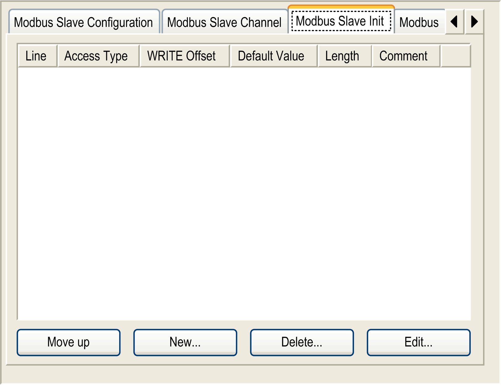
|
|
2 |
Click the button New to create a new initialization value: 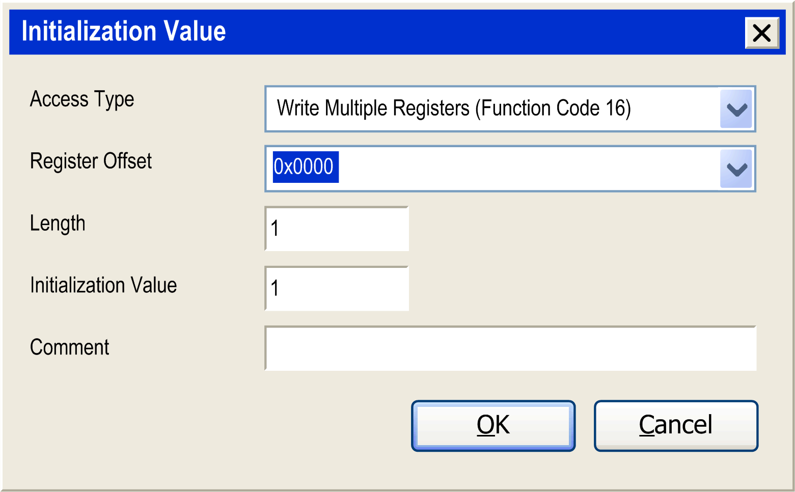
The Initialization Value window contains the following parameters: oAccess Type: Only Write Multiple Register is allowed oRegister Offset: Offset of the %MW that will be initialized oLength: Number of %MW that will be initialized. For example if Offset = 2 and Length = 3, %MW2, %MW3 and %MW4 wil be initialized oInitialization Value: Value the registers are initialized with oComment: Add a comment about this initialization |
|
3 |
Click the Move up or Move down button to change the position of an initialization in the list. Click the Delete button to remove an initialization in the list. Click the Edit button to change the parameters of an initialization. |
|
4 |
Click OK to create a new Initialization Value. |
These next set of interface windows show the mapping of the objects generated by the defined channels. If channel 1 and channel 2 are configured as pictured in the following two graphics, then the Modbus Master I/O Mapping is as pictured in the third graphic below:
