Grounding the M241 System
Overview
To help minimize the effects of electromagnetic interference, cables carrying the fast I/O, analog I/O, and field bus communication signals must be shielded.
| WARNING | |
|---|---|
1Multipoint grounding is permissible (and in some cases inevitable) if connections are made to an equipotential ground plane dimensioned to help avoid cable shield damage in the event of power system short-circuit currents.
The use of shielded cables requires compliance with the following wiring rules:
-
For protective ground connections (PE), metal conduit or ducting can be used for part of the shielding length, provided there is no break in the continuity of the ground connections. For functional ground (FE), the shielding is intended to attenuate electromagnetic interference and the shielding must be continuous for the length of the cable. If the purpose is both functional and protective, as is often the case for communication cables, the cable must have continuous shielding.
-
Wherever possible, keep cables carrying one type of signal separate from the cables carrying other types of signals or power.
Protective Ground (PE) on the Backplane
The protective ground (PE) should be connected to the conductive backplane by a heavy-duty wire, usually a braided copper cable with the maximum allowable cable section.
Shielded Cables Connections
Cables carrying the fast I/O, analog I/O, and field bus communication signals must be shielded. The shielding must be securely connected to ground. The fast I/O and analog I/O shields may be connected either to the functional ground (FE) or to the protective ground (PE) of your M241 Logic Controller. The field bus communication cable shields must be connected to the protective ground (PE) with a connecting clamp secured to the conductive backplane of your installation.
| WARNING | |
|---|---|
The shielding of the Modbus cable must be connected to the protective ground (PE).
| DANGER | |
|---|---|
Protective Ground (PE) Cable Shielding
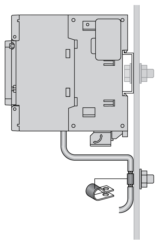
To ground the shield of a cable through a grounding clamp:
|
Step |
Description |
|
|---|---|---|
|
1 |
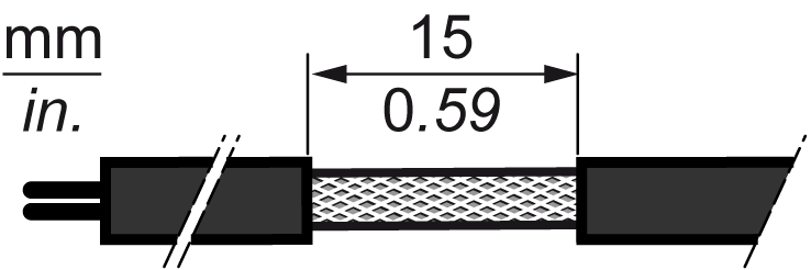
Strip the shielding for a length of 15 mm (0.59 in.). |
|
|
2 |
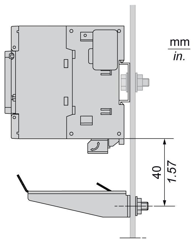
Attach the cable to the conductive backplane plate by attaching the grounding clamp to the stripped part of the shielding as close as possible to the M241 Logic Controller system base. |
|
Functional Ground (FE) Cable Shielding
To connect the shield of a cable through the Grounding Bar:
|
Step |
Description |
|
|---|---|---|
|
1 |
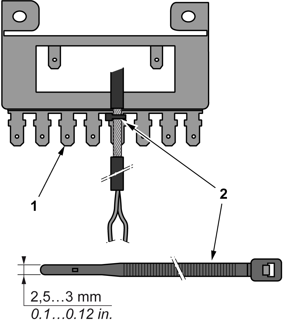
Install the Grounding Bar directly on the conductive backplane below the M241 Logic Controller system as illustrated. |
|
|
2 |
Strip the shielding for a length of 15 mm (0.59 in.). |
|
|
3 |
Tightly clamp on the blade connector (1) using nylon fastener (2)(width 2.5...3 mm (0.1...0.12 in.)) and appropriate tool. |
|