Adding a Device on the Modbus Serial IOScanner
Adding a Device on the Modbus IOScanner
To add a device on the Modbus IOScanner, select the in the , drag it to the , and drop it on the node of the .
For more information on adding a device to your project, refer to:
• Using the Hardware Catalog
• Using the Contextual Menu or Plus Button
%IWx and %QWx of the Modbus Serial Master I/O Mapping tab.
Configuring a Device Added on the Modbus IOScanner
To configure the device added on the Modbus IOScanner, proceed as follows:
|
Step |
Action |
|---|---|
|
1 |
In the , double-click . Result: The configuration window is displayed. 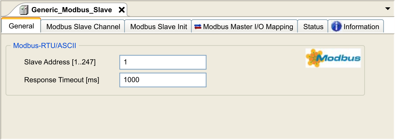
|
|
2 |
Enter a Slave Address value for your device (choose a value from 1 to 247). |
|
3 |
Choose a value for the Response Timeout (in ms). |
To configure the Modbus Slave Channels, proceed as follows:
|
Step |
Action |
|---|---|
|
1 |
Click the Modbus Channels tab: 
|
|
2 |
Click the button: 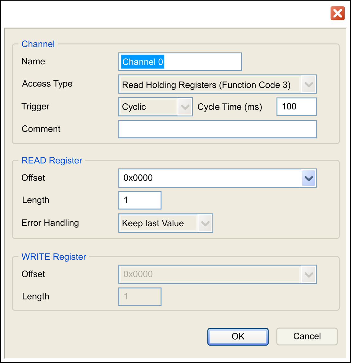
|
|
3 |
Configure an exchange: In the area Channel, you can add the following values:
In the area (if your channel is Read or Read/Write one), you can configure the
In the area (if your channel is Write or Read/Write one), you can configure the
|
|
4 |
Click OK to validate the configuration of this channel.
NOTE: You can also:
Result: The configured channels are displayed: 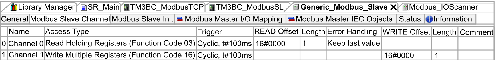
|
To configure your , proceed as follows:
|
Step |
Action |
|---|---|
|
1 |
Click the Modbus Slave Init tab: 
|
|
2 |
Click New to create a new initialization value: 
The Initialization Value window contains the following parameters:
|
|
3 |
Click OK to create a new Initialization Value.
NOTE: You can also:
|
To configure your Modbus Master I/O Mapping, proceed as follows:
|
Step |
Action |
|---|---|
|
1 |
Click the Modbus Master I/O Mapping tab: 
|
|
2 |
Double-click in a cell of the Variable column to open a text field. Enter the name of a variable or click the browse button [...] and chose a variable with the Input Assistant. |
|
3 |
For more information on I/O mapping, refer to EcoStruxure Machine Expert Programming Guide. |
Access Types
This table describes the different access types available:
|
Function |
Function Code |
Availability |
|---|---|---|
|
Read Coils |
1 |
|
|
Read Discrete Inputs |
2 |
|
|
Read Holding Registers (default setting for the channel configuration) |
3 |
|
|
Read Input Registers |
4 |
|
|
Write Single Coil |
5 |
|
|
Write Single Register |
6 |
|
|
Write Multiple Coils |
15 |
|
|
Write Multiple Registers (default setting for the slave initialization) |
16 |
|
|
Read/Write Multiple Registers |
23 |
|