J1939 Interface Configuration
CAN Bus Configuration
To configure the bus of your controller, refer to CAN Bus Configuration.
The CAN bus format is CAN2.0B for J1939.
J1939 Manager Creation and Configuration
Proceed as follows to create and configure a J1939 Manager, if not already present, below the node:
|
Step |
Action |
|---|---|
|
1 |
Click the button |
|
2 |
In the window, select and click the button. For more information on adding a device to your project, refer to: • Using the Hardware Catalog • Using the Contextual Menu or Plus Button |
|
3 |
Close the window. |
|
4 |
Double-click . Result: The configuration window appears: 
|
|
5 |
To configure the , refer to Programming with EcoStruxure Machine Expert / Device Editors / J1939 Configuration Editor / J1939 Manager Editor / Manager Editor found in the EcoStruxure Machine Expert online help. |
ECU Creation and Configuration
Proceed as follows to create and configure Electronic Control Units (ECUs):
|
Step |
Action |
|---|---|
|
1 |
Click the Plus button |
|
2 |
In the window, select and click the button. For more information on adding a device to your project, refer to: • Using the Hardware Catalog • Using the Contextual Menu or Plus Button |
|
3 |
Close the window. |
|
4 |
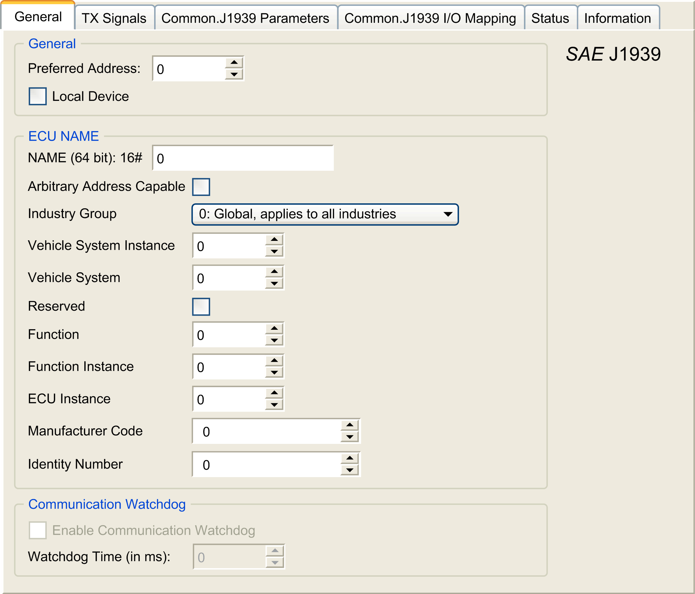
Double-click . Result: The configuration window appears: 
|
|
5 |
To configure the , refer to Configuring J1939 ECUs. |
Configuring J1939 ECUs
As an overview, the following tasks must be generally accomplished:
-
Add one node for each physical J1939 device connected on the CAN bus.
-
For each J1939 device, specify a unique in the range 1...253.
-
For each J1939 device, configure the signals (SPNs) in the tab. These signals are broadcast by the J1939 device to the other J1939 devices.
Refer to the device documentation for information on the supported SPNs.
-
Associate the SPN signals with variables in the tab so that they can be processed by the application.
-
When signals have been added, verify their settings in the window of the tab, for example, , , and . The J1939 protocol does not directly support REAL values, which are instead encoded in the protocol and so must be converted in the application. Similarly, in J1939 units are defined according to the International System of Units (SI) and therefore may need to be converted to values of other unit systems.
Examples:
-
The signal of parameter group has a property Scaling=0.125 that is encoded into a raw variable of type
ARRAY[0..1] OF BYTE. Use the following ST code to convert this to a REAL variable:rRPM:=(Engine_Speed[1]*256 + Engine_Speed[0])*0.125; -
The signal has properties Scaling=0.125 and Unit=km, which are received in a (raw) variable of type
ARRAY[0..3] OF BYTE. Use the following ST code to convert this to a REAL variable in mile units:rTVD := (Total_Vehicle_Distance[3]*EXPT(256,3) +Total_Vehicle_Distance[2]*EXPT(256,2) + Total_Vehicle_Distance[1]*256 +Total_Vehicle_Distance[0])*0.125*0.621371; -
The signal of parameter group has properties Offset=-40 and Unit=C(Celsius), which are received in a (raw) variable of type BYTE. Use the following ST code to convert it to a REAL variable in Fahrenheit units:
rEngineCoolantTemperature := (Engine_Coolant_Temperature - 40)*1.8 + 32;
-
For more details on how to configure the , refer to Programming with EcoStruxure Machine Expert / Device Editors / J1939 Configuration Editor / J1939 ECU Editor / ECU Editor found in the EcoStruxure Machine Expert online help.
Configuring the M251 Logic Controller as an ECU Device
The controller can also be configured as a J1939 ECU device:
|
Step |
Action |
|---|---|
|
1 |
Add a node to the . Refer to ECU Creation and Configuration. |
|
2 |
Select the option in the tab. |
|
3 |
Configure signals sent from the controller to other J1939 devices in the tab. Parameter groups are either of type , that is, sent to all devices, or (Peer-to-Peer), that is, sent to one specified device. |
|
4 |
For signals, configure the of the receiving J1939 ECU device in the parameter group properties window. |
|
5 |
Add signals sent by another J1939 device to the controller in the tab of the J1939 (local) device representing the controller. |
|
6 |
Configure the of the parameter group by specifying the address of the sending J1939 device. |
 next to the