Maximum Hardware Configuration
Introduction
The M262 Logic/Motion Controller is a control system that offers an all-in-one solution for motion applications and a scalable solution for logic applications, with optimized configurations and an open, expandable architecture.
Local and Remote Configuration Principle
The following figure defines the local and remote configurations:

(1) Local configuration
(2) Remote configuration
M262 Logic/Motion Controller Local Configuration Architecture
Optimized local configuration and flexibility are provided by the association of:
-
M262 Logic/Motion Controller
-
TMS expansion modules
-
TM3 expansion modules
Application requirements determine the architecture of your M262 Logic/Motion Controller configuration.
The following figure represents the components of a local configuration:
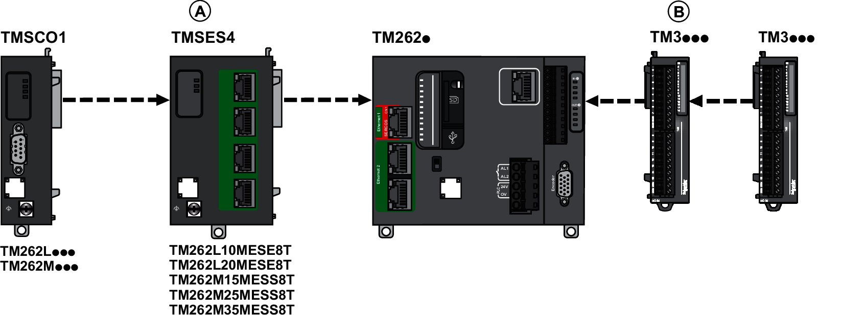
-
1 TMSCO1
for TM262L01MESE8T and TM262M05MESS8T -
3 TMSES4 or 2 TMSES4 and 1 TMSCO1 for the other references
TMSCO1 must be the leftmost module connected to the controller.
(B) TM3 expansion modules (7 maximum).
M262 Logic/Motion Controller Remote Configuration Architecture
Optimized remote configuration and flexibility are provided by the association of:
-
M262 Logic/Motion Controller
-
TMS expansion modules
-
TM3 expansion modules
-
TM3 transmitter and receiver modules
Application requirements determine the architecture of your M262 Logic/Motion Controller configuration.
The following figure represents the components of a remote configuration:
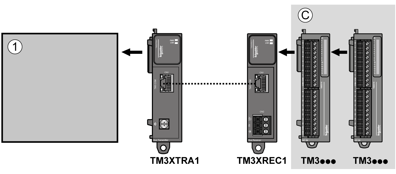
(1) Logic/motion controller and modules
(C) TM3 expansion modules (7 maximum)
M262 Logic/Motion Controller Distributed Configuration Architecture
Optimized remote configuration and flexibility are provided by the association of:
This figure shows the components of a distributed architecture:
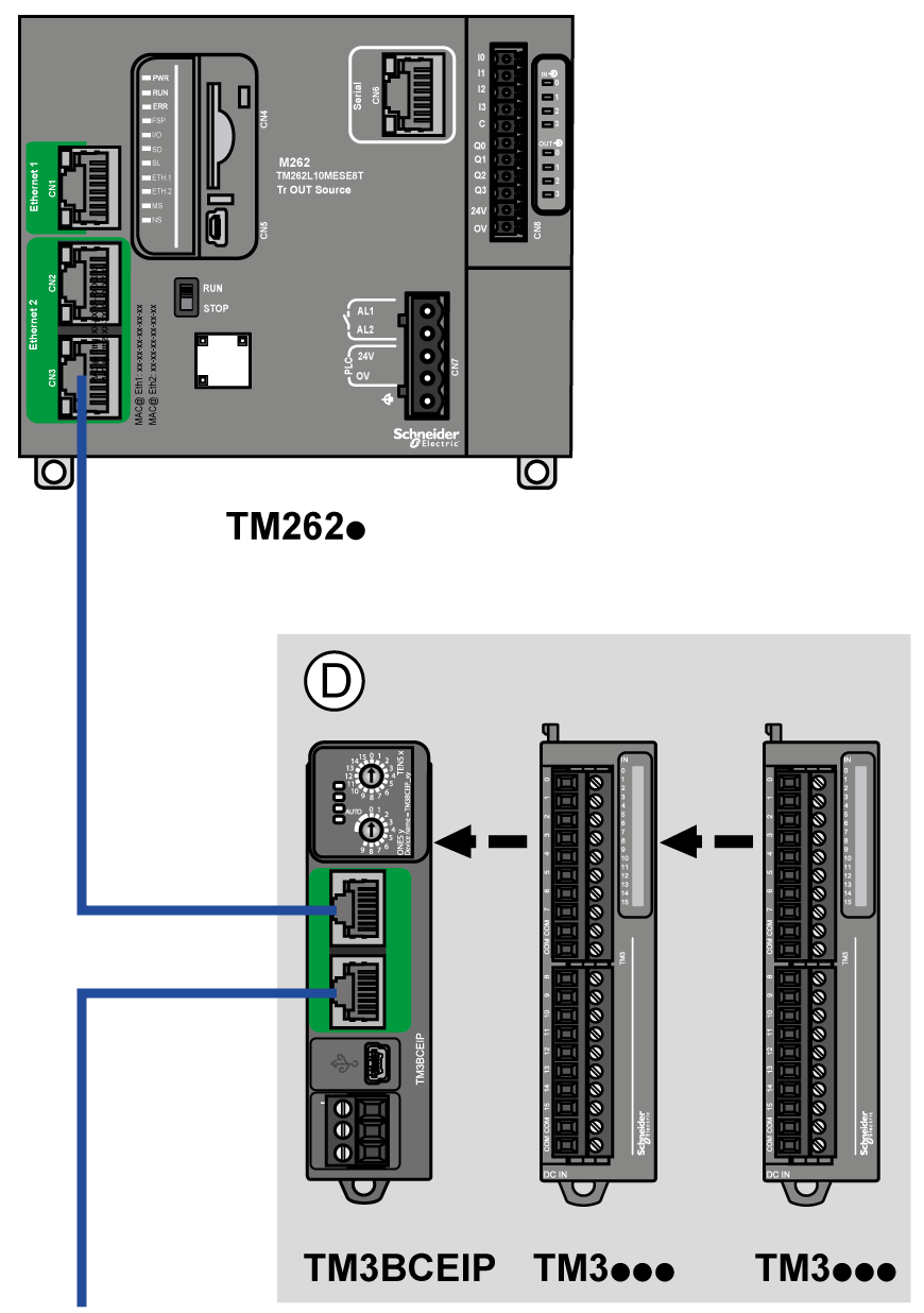
(D) TM3 distributed modules
Maximum Number of Modules
The following table shows the maximum configuration supported:
|
References |
Maximum |
Type of Configuration |
|---|---|---|
|
TM262L01MESE8T TM262M05MESS8T |
7 TM3 expansion modules 1 TMSCO1 |
Local |
|
TM262L10MESE8T TM262M15MESS8T TM262L20MESE8T TM262M25MESS8T TM262M35MESS8T |
7 TM3 expansion modules 3 TMS expansion modules composed of:
|
Local |
|
TM3XREC1 |
7 TM3 expansion modules |
Remote |
|
TM3BCEIP TM3BCSL TM3BCCO |
7 TM3 expansion modules without transmitter and receiver 14 TM3 expansion modules with transmitter and receiver |
Distributed |
|
NOTE: TM3 transmitter and receiver modules are not included in a count of the maximum number of expansion modules.
|
||