Serial Line
Overview
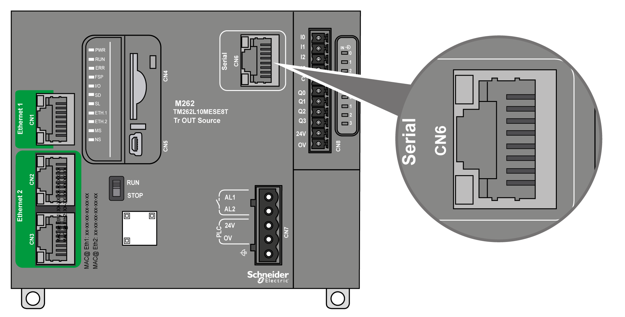
The serial line can be used to communicate with devices supporting the Modbus protocol as either master or slave, ASCII protocol (printer, modem...) and Machine Expert Protocol (HMI,...).

Characteristics
|
Characteristic |
Description |
|
|---|---|---|
|
Function |
RS485 or RS232 software configured |
|
|
Connector type |
RJ45 |
|
|
Isolation |
550 Vac |
|
|
Baud rate |
1200...115200 bps |
|
|
Cable |
Type |
Shielded |
|
Maximum length (between the controller and an isolated junction box) |
30 m (98.43 ft) for RS485 15 m (49.21 ft) for RS232 |
|
|
Polarization |
Software configuration is used to connect 576 Ω polarization resistors when the node is configured as a master. |
|
NOTE: Some devices provide voltage on RS485 serial connections. Do not connect these voltage lines to your controller as they may damage the controller serial port electronics and render the serial port inoperable.
| NOTICE | |
|---|---|
