Ethernet Services
Presentation
This tab displays the list of Ethernet or Sercos devices which are configured to be controlled by Modicon M262 Logic/Motion Controller.
Ethernet_1 and Ethernet_2 Toolbar
The following table describes the toolbar:
|
Element |
Description |
|---|---|
|
|
Allows you to generate the configurations of each device configured in the . |
|
|
Allows you to display more information on the configured devices. |
|
|
Start the Machine Assistant which allows you to discover and to configure the devices. |
Network Settings
To view the configuration of a device, click the tab above the toolbar. The following information displays:
Configured Devices in the Project
|
Element |
Description |
Restriction |
|---|---|---|
|
|
Name of the device from the . Click the device name to access the device configuration. |
Cannot be edited. |
|
|
Type of the device. |
Cannot be edited. |
|
|
IP Address of the device. Can be left blank for Sercos devices |
– |
|
|
MAC address of the target device. Can be left blank for Sercos devices |
Can be edited if selected in the configuration of the device. |
|
|
Hostname of the target device |
Can be edited if selected in the configuration of the device. |
|
|
Subnet mask of the device |
Visible if selected in . |
|
|
Gateway address of the device |
Visible if selected in . |
|
|
Four identification modes are possible: |
– |
|
|
Protocol used |
Cannot be edited. |
|
|
Identifier of the device |
Can be edited for Sercos device. |
|
|
Identification mode of the device |
Can be edited for Sercos device. |
|
|
Three operating modes are possible: |
Can be edited for Sercos device. |
Ethernet Resources
The subtab:
-
Displays the number of configured connections and channels.
-
Displays the number of input words.
-
Displays the number of output words.
-
Displays the scanner load.
IP Routing
The subtab allows you to configure the IP routes in the controller.
The parameter allows you to deactivate the IP forwarding service of the controller. When deactivated, the communication is not routed from a network to another one. The devices on the device network are no longer accessible from the control network and related features like Web pages access on device or commissioning of device via DTM, EcoStruxure Machine Expert - Safety and so on are not possible.
The Modicon M262 Logic/Motion Controller can have up to three Ethernet interfaces. Using a routing table is necessary to communicate with remote networks connected to different Ethernet interfaces. The gateway is the IP address used to connect to the remote network, which needs to be in local network of the controller.
This graphic depicts an example network, in which the last two rows of devices (gray and red) need to be added in the routing table:
Use the routing tables to manage the IP forwarding.
To add a route, double click then click .
For reasons of network security, TCP/IP forwarding is disabled by default. Therefore, you must manually enable TCP/IP forwarding if you want to access devices through the controller. However, doing so may expose your network to possible cyberattacks if you do not take additional measures to protect your enterprise. In addition, you may be subject to laws and regulations concerning cybersecurity.
| WARNING | |
|---|---|
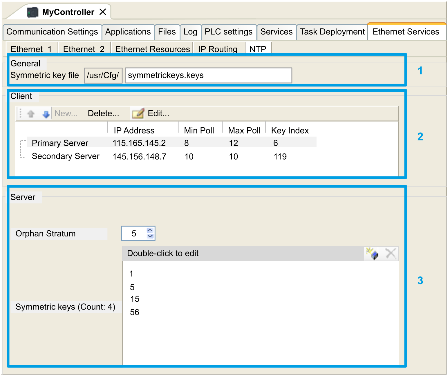
NTP
The NTP Protocol synchronizes the clock of device and resists the effects of variable latency (jitter).
The subtab is divided in three parts:
-
General (1)
-
Client (2)
-
Server (3)
The figure below shows the subtab:
|
Element |
Description |
|
|---|---|---|
|
|
Folder to which the trusted key file is to be uploaded. Not editable. |
|
|
|
File name of the Symmetric keys file. Editable. Can be left empty if no key index is defined.
NOTE: You must enter a valid file name or leave the field empty.
NOTE: The only authentication method for the key algorithm is MD5 for NTP.
|
|
You can define a maximum of two servers : and. You must specify the following information for each server defined.
Element
Description
Value
Constraint
The server IP Address.
Default value: 0.0.0.0
-
The address must be used by another server
-
First byte must be between 1 and 223
-
Loopback address is forbidden
The minimum poll value.
Default value: 6
Value range: 3...17 (1)
Minimum poll value must be inferior to maximum poll value.
The maximum poll value.
Default value: 10
Value range: 3...17 (1)
Maximum poll value must be superior to minimum poll value.
The key index value.
Default value: 0
Value range: 0...65535
0 means “no key index”.
(1): 3 corresponds to 8 seconds (23), 17 corresponds to 131072 seconds (217).
|
Element |
Description |
Value |
Constraint |
||||
|---|---|---|---|---|---|---|---|
|
|
Allows you to enable/disable the NTP Server. |
Checked/unchecked |
You must define stratum for orphan mode or NTP Client Primary Server if NTP Server is enabled. |
||||
|
|
The orphan stratum level. |
Default value: 0 Value range: 0...15 |
0 means: no Orphan Stratum. See Orphan Stratum. |
||||
|
|
The list of key indexes. |
Value range: 1...65535 |
Maximum of 32 key indexes, including Primary Server and Secondary Server key indexes. |
||||
Orphan Stratum
NTP uses a hierarchical system where each level is called a stratum. These levels are assigned a number starting at 0 for the reference at the top level.
When the controller is both client and server, the stratum is calculated automatically from the NTP server it is connected to. When the Orphan Stratum is 0, if the NTP server used by the controller becomes unreachable, the controller indicates to its NTP client that its clock is not synchronized. Otherwise, the value selected is used.
If the controller is only configured as NTP server, it will use the selected value in Orphan Stratum. You should select an appropriate stratum value according to the NTP hierarchy of your architecture.
NTP Keys File Syntax Usage
-
NTP keys file only supports MD5 hash algorithm.
-
The keys file must not have a header.
-
No spaces allowed at the beginning line of a key.
-
If you insert a comment at the end of a key line, you must add two spaces between the end of the key and the beginning of the comment.
Key file syntax examples:
MD5 3N:}7LtY<Uz+FG5y65c4 # MD5 hash algorithm MD5 37R}sQ^~)S~F*HZY(/w\ # MD5 hash algorithm MD5 Mv4[@;x$f:D"_5_l>]t{ # MD5 hash algorithm MD5 ':CHFQ^DvQ0JlAjhP\4, # MD5 hash algorithm MD5 &`!~)4Oem@Xz|M{Hb&bY # MD5 hash algorithm