Introduction
These expansion modules have a built-in removable spring or screw terminal block for the connection of inputs and power supply.
Wiring Diagram
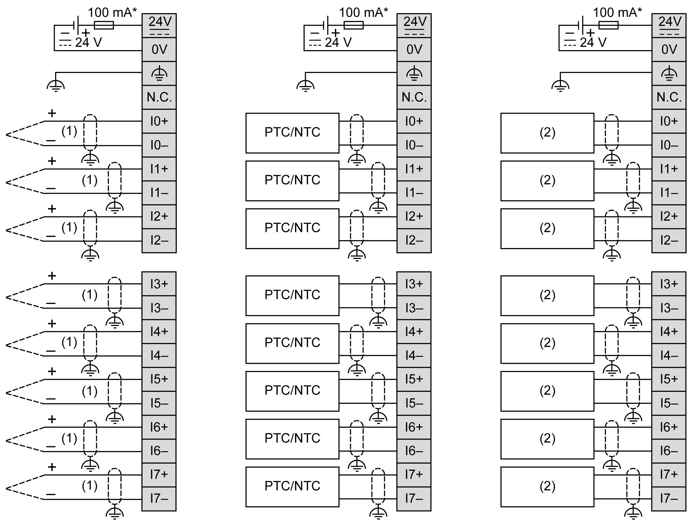
The following figure illustrates the connection between the inputs, the sensors, and their commons:

* Type T fuse
(1) Thermocouple
(2) Resistor
|
WARNING
|
|
UNINTENDED EQUIPMENT OPERATION
Do not connect wires to unused terminals and/or terminals indicated as “No Connection (N.C.)”.
Failure to follow these instructions can result in death, serious injury, or equipment damage.
|