TM3 CANopen Bus Coupler Presentation
Overview
The TM3 CANopen bus coupler is a device designed to manage CANopen communication when using TM2/TM3 I/O expansion modules in a distributed architecture.
The main elements of the TM3 CANopen bus coupler are:
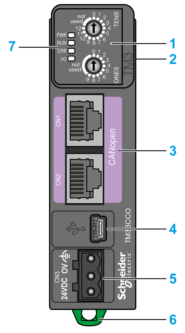
1 Rotary switches
2 Expansion connector for TM2/TM3 I/O expansion modules
3 Two (2) isolated RJ45 CANopen ports (daisy-chained)
4 USB mini-B configuration port
5 24 Vdc power supply
6 Clip-on lock for 35 mm (1.38 in.) top hat section rail (DIN rail)
7 Status LEDs
Main Characteristics
|
Characteristic |
Value |
|---|---|
|
Nominal supply voltage |
24 Vdc |
|
Weight |
100 g (3.53 oz) |
|
Rotary switch |
2 |
|
CANopen port |
2 isolated RJ45 ports for CANopen (daisy-chained). |
|
Power supply connection type |
Removable screw terminal block |
Status LEDs
The following graphic shows the LEDs of TM3 CANopen bus coupler:

The following table describes the status LEDs:
|
LED |
Color |
Status |
Description |
|---|---|---|---|
|
PWR |
Green |
On |
Power is applied. |
|
Off |
Power is removed. All LED indicators are off. |
||
|
RUN |
Green |
On |
Device status is operational. |
|
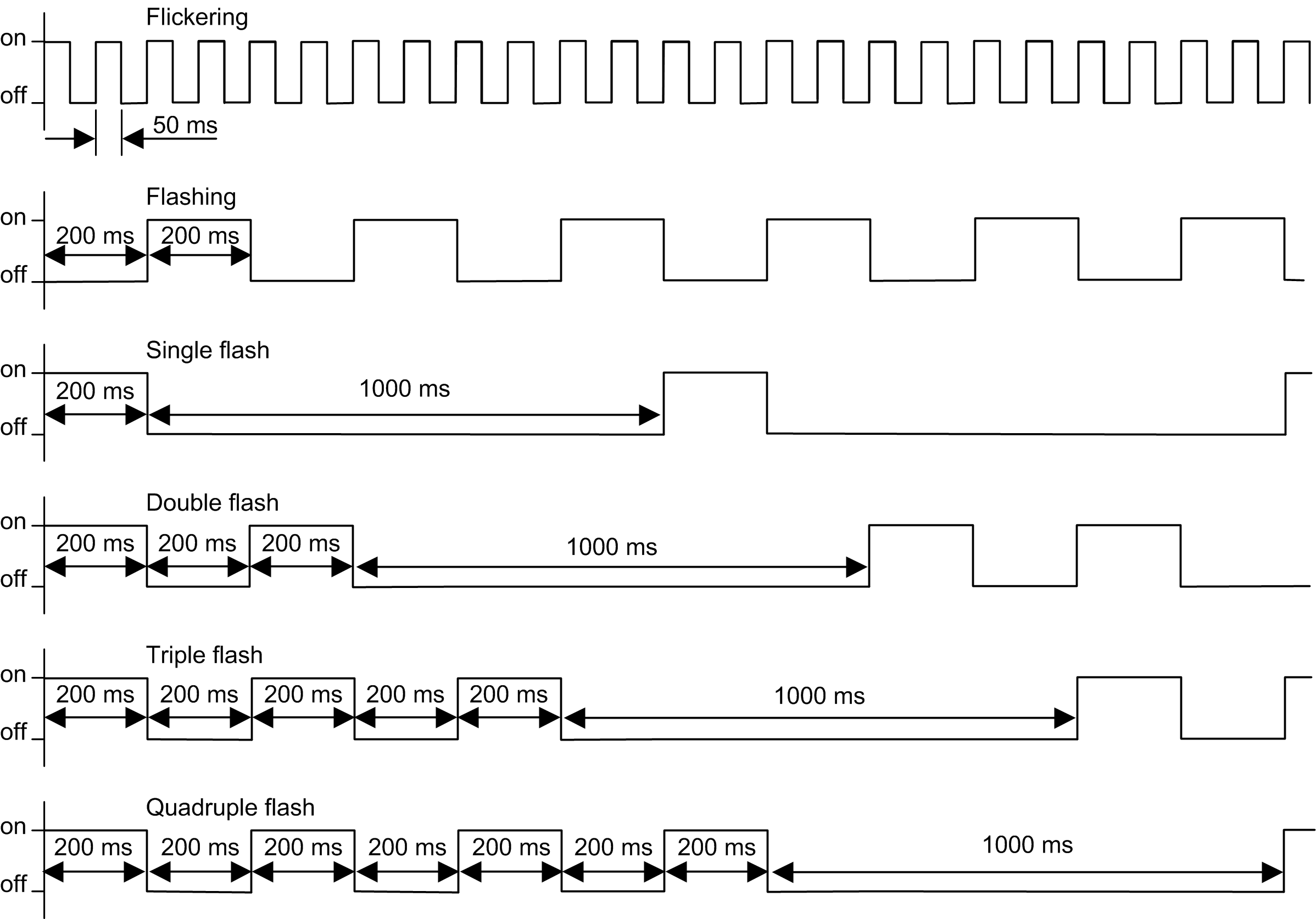
Flickering |
In conjunction with a flickering ERR LED, automatic search for the bus communication speed. |
||
|
Flashing |
Device status is pre-operational. |
||
|
Single flash |
Device status is stopped. |
||
|
Triple flash |
Firmware upgrade. |
||
|
ERR |
Red |
On |
Bus off. |
|
Flickering |
In conjunction with a flickering RUN LED, automatic search for the bus communication speed. |
||
|
Flashing |
Invalid CANopen stack configuration. |
||
|
Single flash |
An internal error counter in the CAN controller has reached or exceeded the error frame limit threshold (error frame). |
||
|
Double flash |
Error control event detected. Detection of a guard event (NMT-Slave or NMT-master) or a heartbeat event (Heartbeat consumer). |
||
|
Triple flash |
Synchronization error detected: message not received from sync producer within the defined period. |
||
|
Quadruple flash |
Event-timer error detected: An expected PDO has not been received before the event-timer elapsed. |
||
|
Off |
No error detected. |
||
|
I/O |
Green |
Flashing |
Device has received and applied the expansion modules configuration. |
|
On |
Device is communicating with the expansion modules. |
||
|
Red |
Single flash |
Expansion module configuration transfer timeout. |
|
|
Green Red |
Flashing On |
The physical configuration is inconsistent with the software configuration. No data exchange (status and I/O) is occurring. |
|
|
Green Red |
On On |
The physical configuration is inconsistent with the software configuration. I/O data is not applied. |
|
|
Green Red |
On Flashing |
At least one TM2 or TM3 expansion module did not respond to the bus coupler for 10 consecutive cycles. |
|
|
Off |
No configuration. Device is not communicating with the expansion modules. |
This timing diagram shows the different LEDs flashing behaviors: