TM3XFHSC202 / TM3XFHSC202G Module Configuration
Accessing the I/O Configuration Window
Follow these steps to access the I/O configuration window:
|
Step |
Description |
|---|---|
|
1 |
In the Devices tree, under the node, double-click the module name. |
|
2 |
Select the tab. |
Configuration of Inputs
This figure shows the tab for inputs:
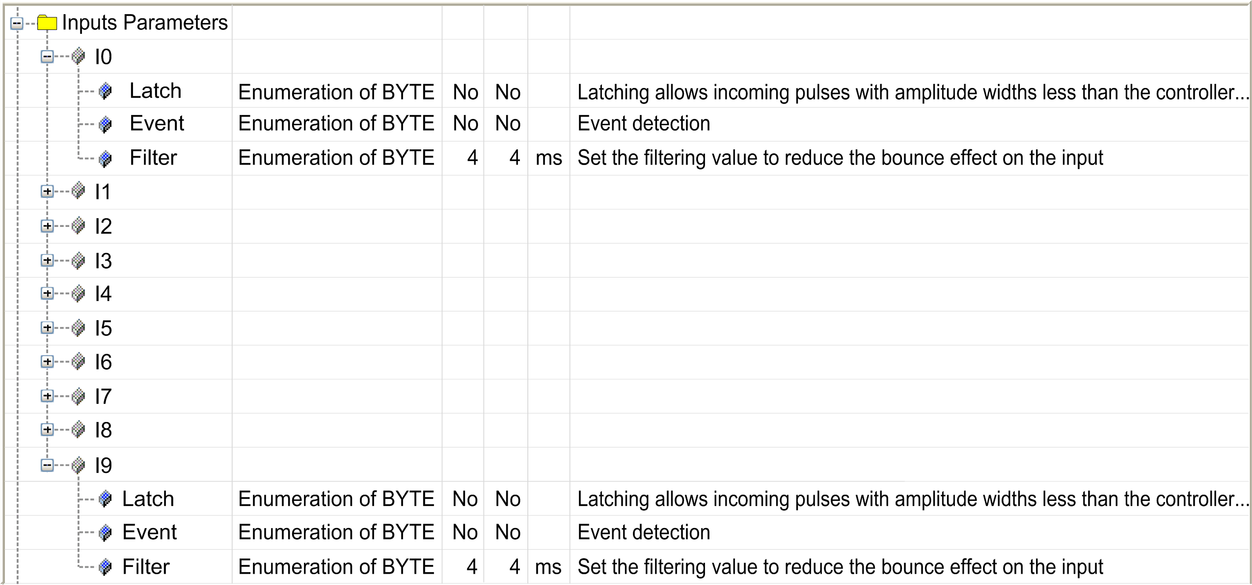
For each input not used by a counting function, you can configure the following parameters:
|
Parameter |
Value |
Description |
Constraint |
|---|---|---|---|
|
|
No* Yes |
Allows incoming pulses with amplitude widths shorter than the controller scan time to be captured and recorded. |
Available if disabled. Use latch inputs in MAST task only. |
|
|
No*
|
Event detection |
Available if:
|
|
|
– |
Allows you to name the external event to reference in a task to use the input event. |
Available if different than no. 49 characters maximum. To use this event you must create an task and give it the same name than the event. |
|
|
0.000 ms 0.001 ms 0.002 ms 0.005 ms 0.01 ms 0.05 ms 0.08 ms 0.5 ms 1 ms 4 ms* 12 ms |
Reduces the effect of noise on a controller input. |
– |
|
* Parameter default value |
|||
Configuration of Outputs
This figure shows the tab for outputs:
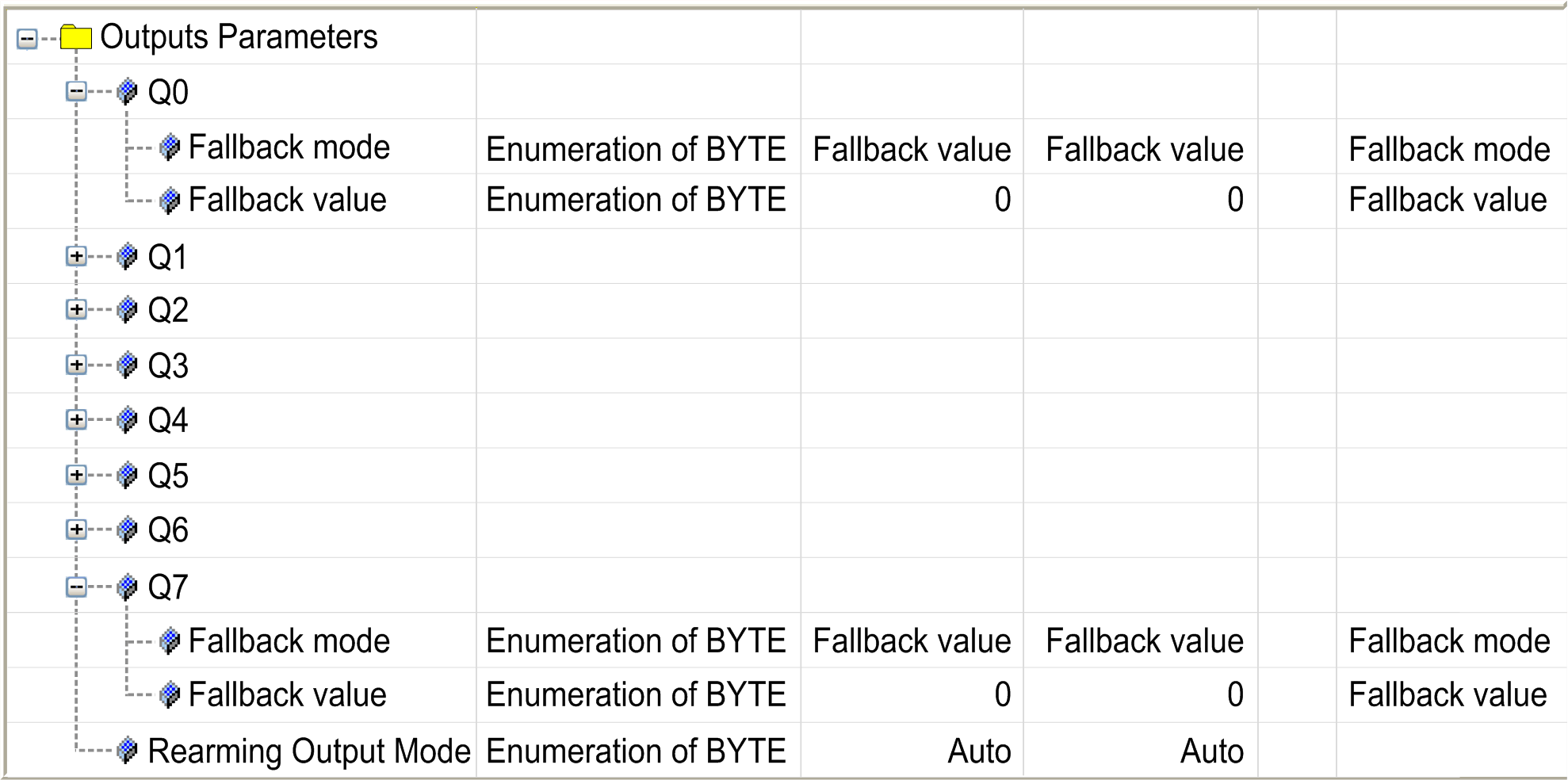
This table presents the function of the different parameters:
|
Parameter |
Value |
Description |
|
|---|---|---|---|
|
|
* |
configured |
not configured |
|
Allows you to set the fallback mode when:
NOTE: is disabled.
|
Allows you to set the fallback mode when the connection between the controller and the module is lost. |
||
|
|
0* 1 |
Allows you to set the fallback value. Available if set to . |
|
|
|
*
|
Select the rearming output mode:
|
|
|
* Parameter default value |
|||
In the case of a short-circuit or current overload, the common group of outputs automatically enters into thermal protection mode (all outputs in the group are set to 0), and are then periodically rearmed (each 10 seconds) to test the connection state. However, you must be aware of the effect of this rearming on the machine or process being controlled.
| WARNING | |
|---|---|