TM3SAFL5R / TM3SAFL5RG Presentation
The main characteristics of the TM3SAFL5R (screw) and TM3SAFL5RG (spring) modules are:
o2 channels
o24 Vdc
oRemovable screw or spring terminal
This table describes the main characteristics of the TM3SAFL5R• module:
|
Characteristic |
Value |
||
|---|---|---|---|
|
Number of safety input channels |
2 |
||
|
Start mode |
Monitored / Non-monitored start |
||
|
Supply voltage |
24 Vdc -15...+20 % |
||
|
Number of outputs |
3 parallel relay outputs, stop category 0 |
||
|
Rated output voltage |
24 Vdc / 230 Vac 6 A maximum per output path |
||
|
Connection type |
TM3SAFL5R |
Removable screw terminal block |
|
|
TM3SAFL5RG |
Removable spring terminal block |
||
|
Weight |
190 g (6.70 oz) |
||
This table defines the type and example of applications that can be associated to the TM3SAFL5R• module:
|
Application type |
Application example |
|---|---|
|
oMonitoring 2 channel emergency stop circuits without short-circuit detection oMonitoring 2 channel limit switches on protective guards without short-circuit detection oMonitoring output signal switching devices of safety light curtains (type 4 according to IEC/EN 61496-1) with 2 * PNP transistors oMonitoring 2 * PNP transistors sensors output (proximity switches) |
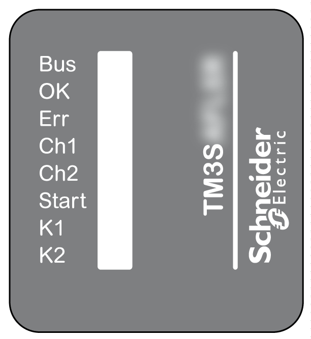
This figure shows the status LEDs:

This table provides the TM3SAFL5R• module status LED indicators description:
|
LED |
Color |
Status |
Description |
|---|---|---|---|
|
Bus |
Green |
Flashing |
The module is receiving the 5 Vdc power supply from the TM3 Bus and the TM3 Bus is functioning. |
|
OK |
Green |
On |
+24 Vdc power supply provided to the module is in the voltage tolerance. |
|
Flashing |
TM3 Bus time-out: the functional safety operation is maintained. |
||
|
Err |
Red |
On |
+24 Vdc power supply provided to the module is out of the voltage tolerance. |
|
Flashing |
TM3 Bus time-out: the safety output is deactivated (off). |
||
|
Ch1 |
Green |
On |
Channel 1 is active: The circuit between S11-S12 is closed or supplied from OSSD output from sensor (PNP). |
|
Ch2 |
Green |
On |
Channel 2 is active: The circuit between S21-S22 is closed or supplied from OSSD output from sensor (PNP). |
|
Start |
Green |
On |
Start condition valid: inputs S11-S12, S21-S22, and S41-S42 (EDM 2) closed/supplied, and S34 or S39 connected to S33. |
|
K1 |
Green |
On |
K1 relay energized (closed) |
|
Flashing |
Waiting for start condition |
||
|
K2 |
Green |
On |
K2 relay energized (closed) |
|
Flashing |
Waiting for start condition |