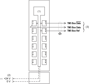
The following figure shows the wiring diagram for the TM5SBET1:

(1) Internal electronics
(2) 24 Vdc I/O power segment integrated into the bus bases
(3) TM5 expansion bus cable (TCSXCNNXNX100)
|
|
|
UNINTENDED EQUIPMENT OPERATION |
|
Properly ground the cable shields as indicated in the related documentation. |
|
Failure to follow these instructions can result in death, serious injury, or equipment damage. |
|
|
|
UNINTENDED EQUIPMENT OPERATION |
|
Do not connect wires to unused terminals and/or terminals indicated as “No Connection (N.C.)”. |
|
Failure to follow these instructions can result in death, serious injury, or equipment damage. |