The TM5 System provides a virtual rack system through a decentralized backplane. The decentralized backplane contains a local configuration and several remote configurations connected together using specific expansion bus cables. The TM5 Transmitter and Receiver electronic modules handle the communication between remote electronic modules via expansion bus cables.
The TM5 Transmitter and Receiver electronic modules need to be associated with a bus base and a terminal block.
The following table gives information about the TM5 Transmitter and Receiver used in the TM5 System:
|
Reference |
Description |
|---|---|
|
Transmits the TM5 data bus. |
|
|
Transmits the TM7 data bus and provides the TM7 power bus to the TM7 expansion I/O blocks. |
|
|
Receives the TM5 data bus, provides power to the 24 Vdc I/O power segment and provides the TM5 power bus to the TM5 expansion I/O blocks. |
|
|
TCSXCNNXNX100 |
Expansion bus cable. |
The TM5 cable used between Transmitter and Receiver modules is the TCSXCNNXNX100 cable, measuring approximately 100 m (328.1 ft). The cable contains two sets of twisted shielded pairs to limit the electromagnetic interference from the power wires to the DATA signal wires. Both pairs are shielded with a common tinned copper foil with an additional drain wire.
The following table describes the characteristics of the individual wire pairs of the cable:
|
Wire |
Characteristic |
Value |
|---|---|---|
|
Pair A |
Conductor cross section (gauge) |
0.34 mm² (22 AWG) |
|
Linear resistance |
55 Ω/km |
|
|
Pair B |
Conductor cross section (gauge) |
0.2 mm² (24 AWG) |
|
Linear resistance |
90 Ω/km |
|
|
Characteristic impedance |
120 Ω |
The following table lists the description of the individual wire pairs of the cable:
|
Wire |
Description |
Color |
|---|---|---|
|
Pair A |
TM5 Power Bus + 5 Vdc (used only for TM5 IP20 towards TM7 IP67) |
Red |
|
TM5 Power Bus 0 Vdc (TM5 bus ref.) |
Black |
|
|
Pair B |
TM5 DATA high |
White |
|
TM5 DATA low |
Blue |
The following table lists the general characteristics of the cable:
|
Characteristic |
Description |
|---|---|
|
Shield |
Tinned copper foil and drain wire |
|
Sheath color |
grey |
|
Operating temperature |
-10 ... +80 °C (14 ... 176 °F) |
|
Storage temperature |
-25 ... +80 °C (-13 ... 176 °F |
|
Overall diameter |
7.4 mm (0.29 in.) ± 0.2 mm (0.007 in.) |
|
Minimum curve radius - fixed applications |
67 mm (2.63 in.) |
|
Fire retardant |
IEC 60332-1 |
|
Low smoke |
VDE 0207-24 |
|
Zero halogen |
EN50290-2-27 |
Implementation of TM5 Transmitter and Receiver Electronic Modules
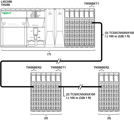
The maximum distance between a Transmitter and a Receiver is 100 m (328.1 ft). The maximum overall distance between the beginning of the local configuration containing a Transmitter and the end of the last remote configuration containing a Receiver is 2500 m (8202.1 ft). The TM5 twisted-pair cable (TCSXCNNXNX100) is required to obtain the maximum distance, the proper electromagnetic resistance and performance required for the communication between Transmitter and Receiver. In addition, the cable must be properly grounded to the functional ground (FE) of your TM5 System.
The following picture presents the TM5 System divided into a local configuration and remote configuration:

(1) Local Configuration
(2) Remote I/O Island Configurations
(3) Expansion bus cable TCSXCNNXNX100
NOTE: For more information to configure Transmitter and Receiver electronic modules refer to Modicon TM5 Expansion Modules Configuration Programming Guide.