TM7 Physical Description
Introduction
The TM7 System consists of IP67 I/O blocks along with field bus, expansion, sensor/actuator and power cables.
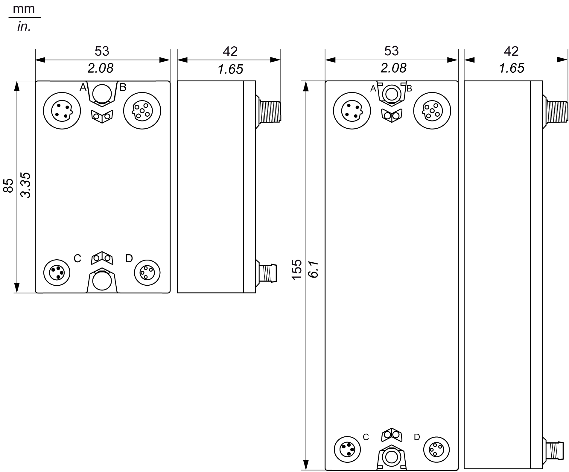
General View of a TM7 I/O Block and Cables
The following figure presents a TM7 I/O block and associated cables:

|
Item |
TM7 Cable Type |
TM7 Block Connector |
|---|---|---|
|
A |
Expansion bus drop cable |
TM7 bus IN |
|
B |
Expansion bus drop cable |
TM7 bus OUT |
|
1...4 |
Sensor or actuator cable |
I/O connectors |
|
C |
Power drop cable |
24 Vdc power IN connector |
|
D |
Power drop cable |
24 Vdc power OUT connector |
| WARNING | |
|---|---|
| NOTICE | |
|---|---|
TM7 Cables References
For more information on the type and length of cables, along with their references, refer to TM7 Cables.
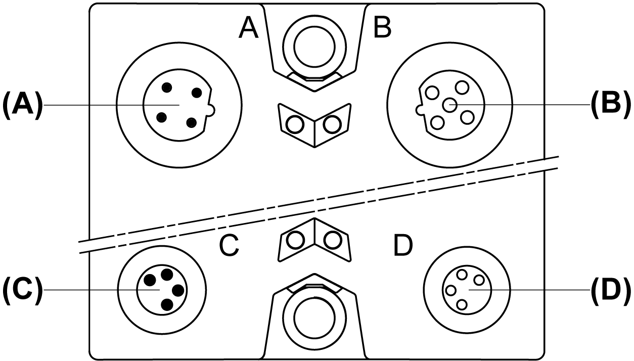
TM7 I/O Blocks Pin and Connector Assignments of Communication and Power Connectors)
The following figure presents the connector assignments of a TM7 I/O block for the communication and power connectors (A, B, C and D):

(A) TM7 bus IN connector M12
(B) TM7 bus OUT connector M12
(C) 24 Vdc power IN connector M8
(D) 24 Vdc power OUT connector M8
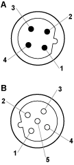
The following figure presents the pin assignments of the TM7 bus IN (A) and OUT (B) connectors:
|
Connection |
Pin |
Designation |
|---|---|---|

|
1 |
TM7 V+ |
|
2 |
TM7 Bus Data |
|
|
3 |
TM7 0 Vdc |
|
|
4 |
TM7 Bus Data |
|
|
5 |
N.C. |
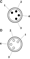
The following figure presents the pin assignments of the 24 Vdc power IN (C) and OUT (D) connectors:
|
Connection |
Pin |
Designation |
|---|---|---|

|
1 |
24 Vdc I/O power segment |
|
2 |
24 Vdc I/O power segment |
|
|
3 |
0 Vdc |
|
|
4 |
0 Vdc |
-
The status of the LED indicators are provided in the Presentation section of the I/O block.
-
The pin assignments of the I/O connectors are provided in the Wiring section of each I/O block.
