The TM5SAI2L and TM5SAI4L expansion electronic modules are 10 Vdc Analog Input electronic modules with 2 and 4 inputs respectively.
If you have wired your input for a voltage measurement, and you configure EcoStruxure Machine Expert for a current type of configuration, you may permanently damage the electronic module.
|
NOTICE |
|
INOPERABLE EQUIPMENT |
|
Verify that the physical wiring of the analog circuit is compatible with the software configuration for the analog channel. |
|
Failure to follow these instructions can result in equipment damage. |
For further information, refer to the Hardware Guide:
|
Reference |
Refer to |
|---|---|
|
TM5SAI2L |
|
|
TM5SAI4L |
The input status is registered with a fixed offset with respect to the network cycle and is transferred in the same cycle.
The electronic module is equipped with a configurable Input cycle. Filtering is deactivated for shorter cycle times.
If the Input cycle is active, then the channels are scanned in ms cycles. The time offset between the channels is 200 µs. The conversion takes place asynchronously to the network cycle.
You can define 2 different type of limits:
oLower limit
oUpper limit
The Lower limit value range is between -32768 to 32767. This value is applied on every channel of the module being configured.
NOTE: the Lower limit cannot be greater than the Upper limit.
|
Channel Configuration |
Digital Value Behavior |
Comments |
|---|---|---|
|
± 10V |
-10 V = -32768 +10 V = +32767 |
If the Lower limit value is configured between -32768 and +32767, the digital value is limited to the Lower limit value. |
|
0...20 mA |
0 mA = 0 20 mA = +32767 |
If the Lower limit value is configured between -32768 and 0, the digital value is limited to 0. If the Lower limit value is configured between 0 and 32 767, the digital value is limited to the Lower limit value. |
|
4...20 mA |
0 mA = -8192 4 mA = 0 20 mA = +32767 |
If the Lower limit is configured between -32768 and -8192, the digital value is limited to -8192. If the Lower limit is configured between -8192 and 32767, the digital value is limited to the Lower limit value. |
The Upper limit value range is between -32768 to 32767. This value is applied on every channel of the module being configured.
NOTE: The Upper limit value cannot be less than the Lower limit value.
|
Channel Configuration |
Digital Value Behavior |
Comments |
|---|---|---|
|
± 10V |
-10 V = -32768 +10 V = +32767 |
If the Upper limit value is configured between -32768 and +32767, the digital value is limited to the Upper limit value. |
|
0...20 mA |
0 mA = 0 20 mA = +32767 |
If the Upper limit value is configured between -32768 and 0, the digital value stays at 0; hence, set the Upper limit value to a positive value. If the Upper limit value is configured between 1 and +32767, the digital value is limited to the Upper limit value. |
|
4...20 mA |
0 mA = -8192 4 mA = 0 20 mA = +32767 |
If the Upper limit value is configured between -32768 and -8192, the digital value is limited to -8192. If the Upper limit value is configured between -8192 and 32767, the digital value is limited to the Upper limit value. |
The input value is evaluated according to the filter level. An input ramp limitation can then be applied using this evaluation.
Formula for the evaluation of the input value:

The following examples show the function of the input ramp limitation based on an input jump and a disturbance.
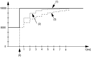
Example 1: The input value makes a jump from 8000 to 16000. The diagram displays the evaluated value with the following settings:
Input ramp limitation = 0
Filter level = 2 or 4

1 Input value.
2 Evaluated value: Filter level 2
3 Evaluated value: Filter level 4
4 Input jump
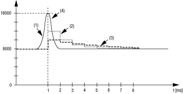
Example 2: A disturbance is imposed on the input value. The diagram shows the evaluated value with the following settings:
Input ramp limitation = 0
Filter level = 2 or 4

1 Input value
2 Evaluated value: Filter level 2
3 Evaluated value: Filter level 4
4 Disturbance (Spike)
Input ramp limitation can only take place when a filter is used. Input ramp limitation is executed before filtering takes place.
The amount of the change in the input value is verified to make sure the specified limits are not exceeded. If the values are exceeded, the adjusted input value is equal to the old value ± the limit value.
The input ramp limitation is well suited for suppressing disturbances (spikes). The following examples show the function of the input ramp limitation based on an input jump and a disturbance.
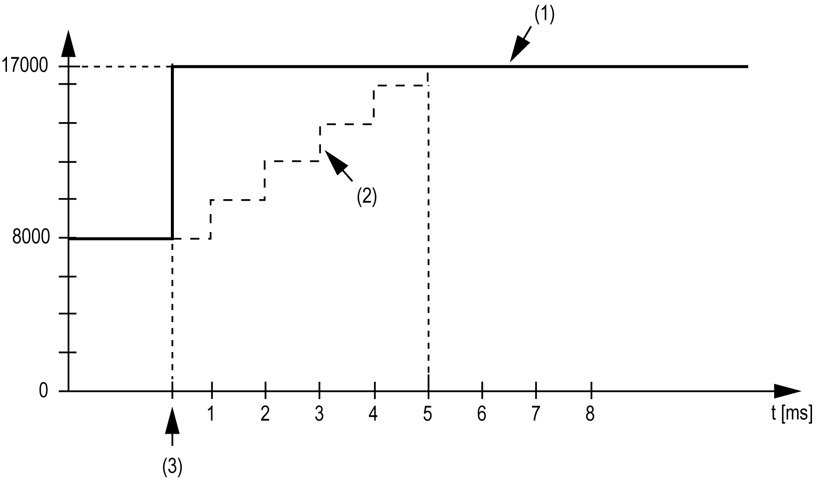
Example 1: The input value makes a jump from 8,000 to 17,000. The diagram displays the adjusted input value for the following settings:
Input ramp limitation = 2047
Filter level = 2

1 Input value
2 Internal adjusted input value before filter
3 Input jump
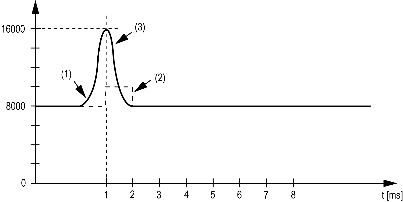
Example 2: A disturbance is imposed on the input value. The diagram shows the adjusted input value with the following settings:
Input ramp limitation = 2047
Filter level = 2

1 Input value
2 Internal adjusted input value before filter
3 Disturbance (Spike)
Variables can be defined and named in the TM5 Module I/O Mapping tab. Additional information such as topological addressing is also provided in this tab.
This table describes the I/O mapping configuration:
|
Channel |
Type |
Description |
|---|---|---|
|
ModuleOK |
BYTE |
State of the compact I/O and electronic modules |
|
DcOk |
BOOL |
Voltage range: o0: Invalid o1: Valid |
|
reserved |
BOOL |
Reserved. |
|
NetworkOk |
BOOL |
TM5 bus: o0: Bus error o1: OK |
|
I/O Data valid |
BOOL |
Data validity: o0: Valid o1: Invalid |
|
reserved |
BOOL |
Reserved |
|
reserved |
BOOL |
Reserved |
|
reserved |
BOOL |
Reserved |
|
reserved |
BOOL |
Reserved |
|
- |
StatusInput00 |
BYTE |
Status of analog input channels (see description below) |
|
Inputs |
AnalogInput00 |
INT |
Current value of the input 0 |
|
... |
... |
||
|
AnalogInput03 |
Current value of the input 3 |
For further generic descriptions, refer to User-Defined Parameters Tab Description.
The StatusInput00 byte describes the status of each input channel:
|
Bit |
Description |
Bits value |
|---|---|---|
|
0-1 |
Channel 00 status |
00: No error detected 01: Below lower limit value1 10: Above upper limit value 11: Wire break2 |
|
2-3 |
Channel 01 status |
|
|
4-5 |
Channel 02 status |
|
|
6-7 |
Channel 03 status |
|
|
1 Channel Configuration 4...20 mA 2 Channel Configuration ± 10V Default setting: The input value has a lower limit. Underflow monitoring is, therefore, not necessary. After lower limit value changes: The input value is limited to the set value. The status bit is set when the lower limit value is passed. |
||
NOTE: The bit dedicated to channel 2 and channel 3 are not used (bit=0) for the TM5SAI2L.
This table describes the TM5SAI2L and TM5SAI4L user-defined parameters configuration:
|
Name |
Value |
Default Value |
Description |
|---|---|---|---|
|
InputFilter |
off level 2 level 4 level 8 level 16 level 32 level 64 level 128 |
off |
Specifies the filter time of all digital inputs |
|
InputLimitation |
16383 off 4095 511 8191 1023 2047 255 |
16383 |
Defines the input ramp limitation of the input filter. |
|
ChannelType01 |
-10 V to +10 V 0 to 20 mA 4 to 20 mA |
-10 V to +10 V |
Specifies the channel type. |
|
ChannelType02 |
-10 V to +10 V 0 to 20 mA 4 to 20 mA |
-10 V to +10 V |
Specifies the channel type. |
|
ChannelType03(1) |
-10 V to +10 V 0 to 20 mA 4 to 20 mA |
-10 V to +10 V |
Specifies the channel type. |
|
ChannelType04(1) |
-10 V to +10 V 0 to 20 mA 4 to 20 mA |
-10 V to +10 V |
Specifies the channel type. |
|
LowerLimit |
-32767 |
-32767 |
Specifies the lower measurement limit. |
|
UpperLimit |
32767 |
32767 |
Specifies the upper measurement limit. |
|
(1) For TM5SAI4L. |
|||