The TM5SE1IC02505 expansion electronic module is a 5 Vdc or 24 Vdc Expert Inputs electronic module with 1 input channel for ABR incremental encoder.
The encoder signal is counted as shown below:
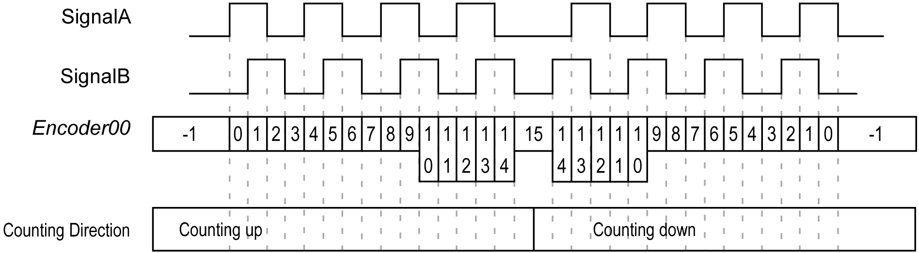
For further information, refer to TM5SE1IC02505 Electronic Module 1 HSC INC 250 kHz 5 Vdc.
Variables can be defined and named in the TM5 Module I/O Mapping tab. Additional information such as topological addressing is also provided in this tab.
This table describes the I/O mapping configuration:
|
Channel |
Type |
Description |
|---|---|---|
|
ModuleOK |
BYTE |
State of the compact I/O and electronic modules |
|
DcOk |
BOOL |
Voltage range: o0: Invalid o1: Valid |
|
reserved |
BOOL |
Reserved. |
|
NetworkOk |
BOOL |
TM5 bus: o0: Bus error o1: OK |
|
I/O Data valid |
BOOL |
Data validity: o0: Valid o1: Invalid |
|
reserved |
BOOL |
Reserved |
|
reserved |
BOOL |
Reserved |
|
reserved |
BOOL |
Reserved |
|
reserved |
BOOL |
Reserved |
|
- |
PowerSupply |
BYTE |
Status encoder supply |
|
|
|
PowerSupply01 |
BOOL |
Status encoder supply 24 Vdc (0 = OK) |
|
|
PowerSupply02 |
Status encoder supply 5 Vdc (0 = OK) |
|||
|
Inputs |
Inputs |
BYTE |
State of all digital inputs (bits 6...7: not used) |
|
|
|
SignalA |
BOOL |
Encoder Signal A |
|
|
SignalB |
BOOL |
Encoder Signal B |
||
|
SignalR |
BOOL |
Encoder Reference Impulse |
||
|
reserved |
BOOL |
reserved |
||
|
DigitalInput01 |
BOOL |
State of digital input 0 |
||
|
DigitalInput02 |
BOOL |
State of digital input 1 |
||
|
reserved |
BOOL |
reserved |
||
|
reserved |
BOOL |
reserved |
||
|
- |
Encoder01 |
DINT |
Incremental encoder |
|
|
- |
StatusInput01 |
BYTE |
Status incremental encoder 01 (see below) |
|
|
- |
ReferenceModeEncoder01 |
BYTE |
Reference mode incremental encoder 01 |
|
For further generic descriptions, refer to User-Defined Parameters Tab Description.
This register contains information regarding whether the referencing process is off, active, or complete.
This table describes the StatusInput01 register:
|
Bit |
Description |
|---|---|
|
0-1 |
Always 0. |
|
2 |
When the referencing is ON, this bit is always 1 after the first reference impulse. When the referencing is OFF, this bit is always 0. |
|
3 |
When the referencing is ON, this bit toggles after each completed reference. When the referencing is OFF, this bit is always 0. |
|
4 |
This bit is always 1 after the first reference impulse. |
|
5...7 |
Free-running counter, increased with each reference impulse. |
Example:
|
Register Value |
Description |
|
|---|---|---|
|
00000000 bin |
00 hex |
Referencing off or already in progress. |
|
00111100 bin |
3C hex |
First reference complete, reference value applied in the Encoder00 register. |
|
xxx11100 bin |
xB hex |
Bits 5...7 are changed sequentially with each reference impulse. |
|
xxx1x100 bin |
xx hex |
Bits changed continuously with the continuous referencing setting. With every reference impulse, the reference value is applied to the Encoder00 register. |
ReferenceModeEncoder01 Register
This register determines the encoder reference mode.
This table describes the ReferenceModeEncoder01 register:
|
Bit |
Value |
Description |
|---|---|---|
|
0-1 |
00 |
Referencing OFF |
|
01 |
One-time reference (single shot) |
|
|
11 |
Continuous referencing |
|
|
2...5 |
0000 |
Bit permanently set = 0 |
|
6-7 |
00 |
Referencing OFF |
Example:
|
Register Value |
Description |
|
|---|---|---|
|
00000000 bin |
00 hex |
Referencing OFF |
|
11000001 bin |
C1 hex |
One-time reference (single shot). When starting over after the referencing process is complete, set this register to 00 hex. Then wait until the StatusInput00 also takes on the value x0 hex. |
|
11000011 bin |
C3 hex |
Continuous referencing: referencing occurs at every reference pulse. |
This table describes the TM5SE1IC02505 user-defined parameters configuration:
|
Name |
Value |
Default Value |
Description |
|---|---|---|---|
|
PresetABR01_32Bit |
-2,147,483,648...2,147,483,647 |
0 |
Homing preset value for counter; the value set here is applied to the counter value upon completion of the referencing process. |
|
ReferenceEdge |
Off rising falling |
Off |
Selects edge of reference pulse for homing. |
|
ReferenceEnableSwitch |
low active high active |
low active |
Digital input 01 configure edge. |
|
ReferenceEnableSwitch |
disabled enabled |
disabled |
Enables/Disables the above parameter |