TMSES4 Presentation
Overview
The TMSES4 Ethernet module provides an additional Ethernet interface to the controller. A maximum of three TMSES4 modules can be configured in the system.
-
TM262L10MESE8T
-
TM262L20MESE8T
-
TM262M15MESS8T
-
TM262M25MESS8T
-
TM262M35MESS8T
The MAC address of the TMSES4 is unique for the three TMSES4, this MAC address is available on the label on the left side of the M262 Logic/Motion Controller.
Main Characteristics
The table describes the main characteristics of the TMSES4 Ethernet communication module:
|
Main Characteristics |
|
|---|---|
|
Standard |
Ethernet |
|
Connector type |
4 RJ45 connectors for Ethernet communication |
|
Transfer rate |
1 Gbit/s maximum |
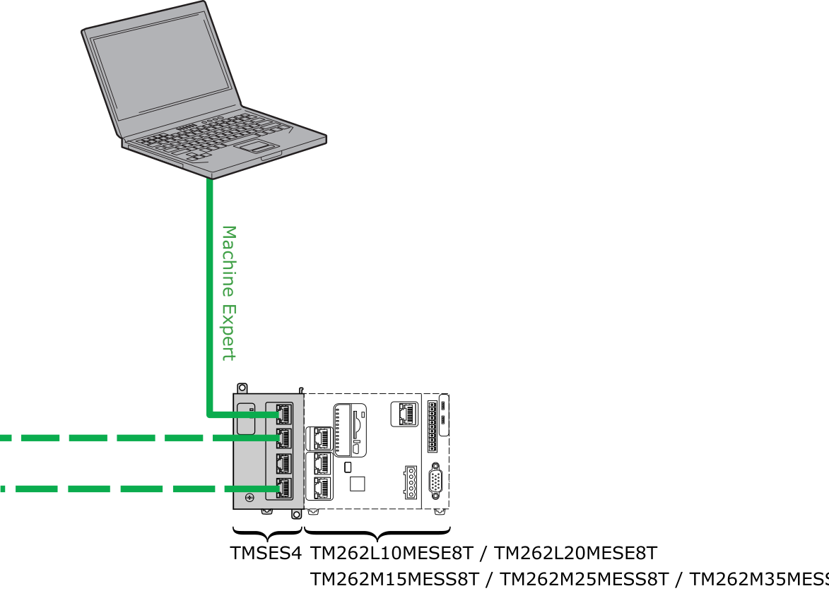
Connection
The following illustration shows the connection of a controller to an Ethernet network:
Module Status LED
The illustration shows the TMSES4 status LEDs:
The table describes the TMSES4status LED:
|
LED |
Color |
Status |
Description |
|---|---|---|---|
|
PWR |
Green |
On |
Power is applied. |
|
Off |
Power is removed. |
||
|
MOD STS |
Green |
On |
The module is running. |
|
Red |
On |
The module is not running. |
|
|
Flashing |
A connection error or network saturation is detected. |
||
|
ETH |
Green |
On |
The module is running and one port is connected. |
|
Flashing |
|
||
|
Off |
The module is initializing. |
RJ45 Connector Status LEDs
The illustration shows the RJ45 connector status LEDs:
The table describes the RJ45 connector status LED:
|
Label |
Description |
LED |
||
|---|---|---|---|---|
|
Color |
Status |
Description |
||
|
1 |
Ethernet activity |
Green |
Off |
No activity |
|
On |
Transmitting or receiving data |
|||
|
2 |
Ethernet link |
Green/Yellow |
Off |
No link |
|
Yellow |
Link at 10 or 100 Mbit/s |
|||
|
Green |
Link at 1 Gbit/s |
|||